*BACHELOR OF ENGINEERING DEGREE/DEGREE WITH HONOURS IN AEROSPACE
SYSTEMS ENGINEERING
*BEng Final Year Project Report
School of Engineering and Technology
University of Hertfordshire
MODELLING AND SIMULATION OF A UH UAV DYNAMICS
Report by
LEONINE .F KUNZWA
Supervisor
DR RASHID ALI
Date
27 April 2011
�DECLARATION STATEMENT
I certify that the work submitted is my own and that any material derived or quoted from the
published or unpublished work of other persons has been duly acknowledged (ref. UPR
AS/C/6.1, Appendix I, Section 2 – Section on cheating and plagiarism)
Student Full Name: LEONINE FUNGAI KUNZWA
Student Registration Number: 08177750
Signed: …………………………………………………
Date: SELECT DATE OF SUBMISSION HERE
�School of Engineering and Technology *BEng Final Year Project Report
ABSTRACT
Static and dynamic stability was defined and the UAV components contribution to static and
dynamic stability was highlighted. The recommended geometric configurations based on
desired stability characteristics were outlined. The Longitudinal and lateral derivatives were
defined, estimated and analysed. They were estimated using the USF stability and control
Datcom (Data Compendium) method. An excel model was used to estimate the motions,
calculate the forces, moments and determine the transfer functions for longitudinal and lateral
modes. A Simulink model1 was developed to predict the dynamic characteristic of the existing
UH UAV (MAK.2). Another Simulink model was developed to overcome the drawbacks of
Simulink model1. The Simulink model was interfaced with flight gear and linked to excel model.
Modelling and simulation of UH-UAV dynamics i
�School of Engineering and Technology *BEng Final Year Project Report
ACKNOWLEDGEMENTS
I thank Dr Rashid Ali for his support, motivation and supervision throughout the year.
I thank my family for supporting me and my parents for their inspiration and encouragement.
I also thank my housemates and friends Mr A Nyakandi, Mr K Kimani, Dr M Choong, Mr R Krish
for providing intellectually stimulating company and constructive criticism.
I thank Mr M Sakarombe and Mrs Kalama for their support.
Modelling and simulation of UH-UAV dynamics ii
�School of Engineering and Technology *BEng Final Year Project Report
TABLE OF CONTENTS
DECLARATION STATEMENT ...................................................................................................... i
ABSTRACT ................................................................................................................................... i
ACKNOWLEDGEMENTS ............................................................................................................ ii
TABLE OF CONTENTS .............................................................................................................. iii
Nomenclature ...............................................................................................................................1
1. Introduction ..........................................................................................................................2
1.1 History and future of UAV .............................................................................................2
1.2 Aims and objectives ......................................................................................................3
1.2.1 UAV specifications ................................................................................................3
1.2.2 Axis System ...............................................................................................................4
2. Static stability and Control ...................................................................................................4
2.1 UAV Static stability (Cmo>0) ........................................................................................4
2.2 UAV Dynamic stability .......................................................................................................5
2.2.1 UAV Oscillatory motion ..............................................................................................5
2.3 UAV Longitudinal static stability and control .....................................................................6
2.3.1 Contribution of aircraft components to stability ..........................................................6
UAV Wings contribution .......................................................................................................6
UAV fuselage contribution ...................................................................................................7
UAV engine contribution ......................................................................................................7
UAV tail contribution ............................................................................................................7
UAV Stick free and stick fixed stability .................................................................................8
Desirable geometry configuration ........................................................................................9
2.4 UAV Longitudinal control...................................................................................................9
2.4.1 Aerodynamic balance ................................................................................................9
2.5 UAV Directional stability ..................................................................................................10
2.5.1 UAV components contribution .................................................................................10
2.6 UAV Directional control ...................................................................................................10
2.6.1 UAV Roll stability .....................................................................................................11
UAV Components contribution ..........................................................................................11
2.6.2 UAV Roll control ...........................................................................................................11
2.6.3 UAV coupling motions .............................................................................................11
3 Aerodynamic Modelling ..........................................................................................................12
3.1 UAV Moment of inertia ....................................................................................................12
3.2 Aerodynamic forces and Derivatives ...............................................................................12
3.2.1 Longitudinal derivatives ..........................................................................................13
3.2.2 The Lateral Derivatives .........................................................................................15
4 UAV Longitudinal motions ......................................................................................................17
Modelling and simulation of UH-UAV dynamics iii
�School of Engineering and Technology *BEng Final Year Project Report
4.1 Derivative influence on longitudinal motion .....................................................................18
5 UAV Lateral motion ................................................................................................................19
6 Models and Simulations .........................................................................................................20
6.1 The UAV generic model 1 ...............................................................................................21
6.2 UAV generic model 2 ......................................................................................................22
6.3 UAV generic model 3 ......................................................................................................23
7 Results ...................................................................................................................................25
7.1 Longitudinal dynamics.....................................................................................................25
7.2 UAV responds to Gust and turbulence ............................................................................27
7.3 Lateral Dynamics ............................................................................................................28
8 The UAV Simulink models ......................................................................................................31
8.1 Simulink Model 1 ..........................................................................................................31
8.2 Simulink model 2 ...........................................................................................................38
8.3 The excel model ..............................................................................................................42
9 Linking Simulink model1 with excel model. .............................................................................43
Summary ....................................................................................................................................45
References .................................................................................................................................47
Bibliography ...............................................................................................................................50
APPENDICES ............................................................................................................................51
Modelling and simulation of UH-UAV dynamics iv
�School of Engineering and Technology *BEng Final Year Project Report
Nomenclature
a -Local speed of sound r -Yaw rate
AR- wing Aspect ratio S -wing reference area
ARt- Tail Aspect ratio Sv- Fin reference area
ARv- Vertical Aspect ratio St -Tailplane reference area
b -Wing span T2 -Time to double amplitude
c -Mean aerodynamic chord (mac) u -Axial velocity
CD -Drag coefficient U -Total axial velocity
CD0- Zero lift drag coefficient v -Lateral velocity
Cl -Rolling moment coefficient V - velocity
CL- Lift coefficient Vv -Fin volume ratio
CLw- Wing lift coefficient Vh-Tailplane volume ratio
CLt -Tail lift coefficient w -Normal velocity
CH -Elevator hinge moment coefficient W- Weight
Cm -Pitching moment coefficient x -Longitudinal coordinate in axis system
Cm0- Pitching moment coefficient about X -Axial force component
wing -ac Y -Lateral force component
Cmα –Cm Cave slope Z -Normal force component
Cn- Yawing moment coefficient Β- Sideslip angle
Cx -Axial force coefficient γ- Flight path angle
Cy -Lateral force coefficient δ -Control angle
Cz- Normal force coefficient ε -Downwash angle at tail plane
e- Oswald efficiency factor ε0 -Zero lift downwash angle at tail
H -Elevator hinge moment ζ -Rudder angle: Damping ratio
Ix -Moment of inertia in roll ζd -Dutch roll damping ratio
Iy -Moment of inertia in pitch ζp- Phugoid damping ratio
Iz -Moment of inertia in yaw ζs- Short period pitching oscillation
Kn- Controls fixed static stability margin damping ratio
lv -Distance from cg to fin ac point η -Elevator angle
lt -Distance from cg to horizontal tail ac θ- Pitch angle
L- Lift Rolling moment λ -Eigenvalue
m- Mass Λ -Wing sweep angle
M -Mach number ξ -Aileron angle
M -Pitching moment ρ -Air density
N- Yawing moment φ- Roll angle
p -Roll rate ψ Yaw angle
q -Pitch rate ω -Undamped natural frequency
Q -Dynamic pressure
Modelling and Simulation of a UH-UAV dynamics 1
�School of Engineering and Technology *BEng Final Year Project Report
1. Introduction
1.1 History and future of UAV
Unmanned Aerial vehicle (UAV) is defined as a “powered aerial vehicle that uses
aerodynamic forces to provide vehicle lift, can fly autonomously or be piloted remotely, can be
expendable or recoverable, and can carry a lethal or nonlethal payload”. [1]
The concept of UAV first started during American civil war. Balloons carrying explosives were
sent to explode in enemy territories. The Japanese also tried the same concept during World
War2. A prototype UAV called Operation Aphrodite was introduced by American defence
during World War 2 as an attempt to fly manned aircrafts in an unmanned mode. However,
the operation wasn’t successful due to lack of technology to control the unmanned vehicle. [2]
The USA military used drones named U-2 and Firebee in 1960s for reconnaissance missions.
The firebee was extensively used for reconnaissance and combat during The Vietnam War. It
was equipped with UV cameras, communications and electronic intelligence.
The increase in technology has resulted in high endurance UAV with full combat capabilities.
For example, the Predator has 40hrs endurance and the Global hawk has 24hrs endurance.
There has been an increase in commercial applications of UAVs. Some of the industries in
which UAVs have gained interest are the agricultural sector where UAVs are beings used to
spray insecticides, fertiliser and for crop monitoring in large fields. [3]
They are also being used in mineral explorations for aerial surveying to find minerals in
otherwise inaccessible areas. Some UAVs are being used for coastline monitoring in marine
and mobile relay platforms in telecommunications. Other civilian uses of UAVs include news
broadcasting, air and ground traffic control for monitoring busy airports and motorways.
According to John Keller, America invested $4.5 billion in 2010 on UAV technology. [4]
There is a vast range of UAV designs and specifications and each suited for its intended
mission. As highlighted above, the use of UAVs is becoming more popular in both defence
and environmental research industries. However, there is still high developmental cost. The
UAV testing phase has the highest budget in the development cycle. [5]
There is also high risk that the UAV might be unstable or fail when subjected to different
parameters. One cannot be absolutely sure whether the UAV meets the specifications without
test flights. This project is a solution to the problems outlined. Modelling the UAV dynamics
will enable a thorough analysis in the behaviour and stability of the UAV at different
conditions. Real time simulations will save time cost and eliminate risk.
The project is to use MathWorks package (Matlab and Simulink) to model the six degrees of
freedom of the dynamics of a particular UAV; and use the model to accurately simulate any
UAV by simply changing the variables. This will be achieved by using the equations of motion.
This approach has been adopted by companies such as BAE systems when developing the
Eagle 150. BAE SYSTEMS Controls Develops Autopilot for Unmanned Aerial Vehicle Using
MathWorks Tools. [6]
Modelling and Simulation of a UH-UAV dynamics 2
�School of Engineering and Technology *BEng Final Year Project Report
1.2 Aims and objectives
Aims:
• To successfully test flight a completed UH UAV.
• To model the six degrees of freedom of the dynamics of the UH UAV.
• To predict the static, dynamic stability and control parameters from the simulation.
Objectives:
• Contributing actively in the construction and test-flight of the UH UAV.
• Completing the UAV simulation before the test flight.
• Estimating longitudinal and lateral stability and control derivatives.
• Developing a UAV model using Matlab and Simulink.
• Applying engineering and mathematical problem solving skills.
• Managing time efficiently by effective time planning.
1.2.1 UAV specifications
The 2011 UH-UAV will be used in the meteorology industry for data collection in the Antarctic.
It will be equipped with some sensors and cameras for data collection and recording.
Specifications
• Operating temperature of -40⁰C
• Endurance of 3hrs
• Top speed of 65 knots
• Radio link radius more than 40km
• Maximum weight of 12kg including engine but excluding fuel and payload
• Has a detachable payload bay (Modular)
• Can accommodate different payload bays
• Autonomous
Modelling and Simulation of a UH-UAV dynamics 3
�School of Engineering and Technology *BEng Final Year Project Report
1.2.2 Axis System
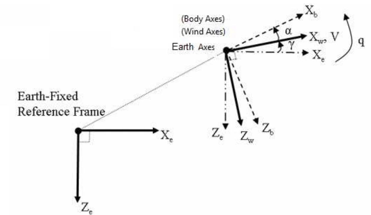
Body axis: The axis is fixed on the UAV’s centre of gravity (CG) and moments of inertia are
constant. xb axis is along the nose, yb axis is along the wing and zb axis points down.
Earth axis: assumes a flat earth and the system is fixed on the surface of the earth. xe,ye,ze
axis corresponding to north, east and earth’s centre. [Figure 1.2.2]
Wind axis: assumes that the applied forces act on the UAV’s centre of gravity.
Figure 1.2.2 axis system (from Matlab help manual by MathWorks 2009)
2. Static stability and Control
The UAV’s state of equilibrium is where the sum of forces and moments at its centre of gravity
are zero.[7]
Stability is the tendency for an aircraft to return to its equilibrium position after a disturbance.
The disturbance can be due to various inputs such as turbulence, gusts winds and pilot
inputs. The UAV must be stable even after being exposed to these external disturbances.
The UAV must be stable in level flight and also manoeuvrable at different speeds to ensure
success of the intended mission. The ability for the UAV to easily achieve this with minimal
workload is considered as its handling qualities. [8]
2.1 UAV Static stability (Cmo>0)
Assuming controls are fixed and displacement is due to atmospheric disturbance.
Static stability is the initial tendency for the UAV to return to its equilibrium position after a
displacement due to external disturbances. If the UAV return to its equilibrium position after a
displacement, then it has positive static stability and if it moves away from its equilibrium
position, then it has negative static stability. If the UAV stays at its new position after a
displacement, it is considered to have neutral static stability. [9]
Positive static stability is stable. Negative static stability is unstable. Neutral static stability is
neither stable nor unstable hence neutral.
Modelling and Simulation of a UH-UAV dynamics 4
�School of Engineering and Technology *BEng Final Year Project Report
2.2 UAV Dynamic stability
Assuming controls are fixed and displacement is due to atmospheric disturbance.
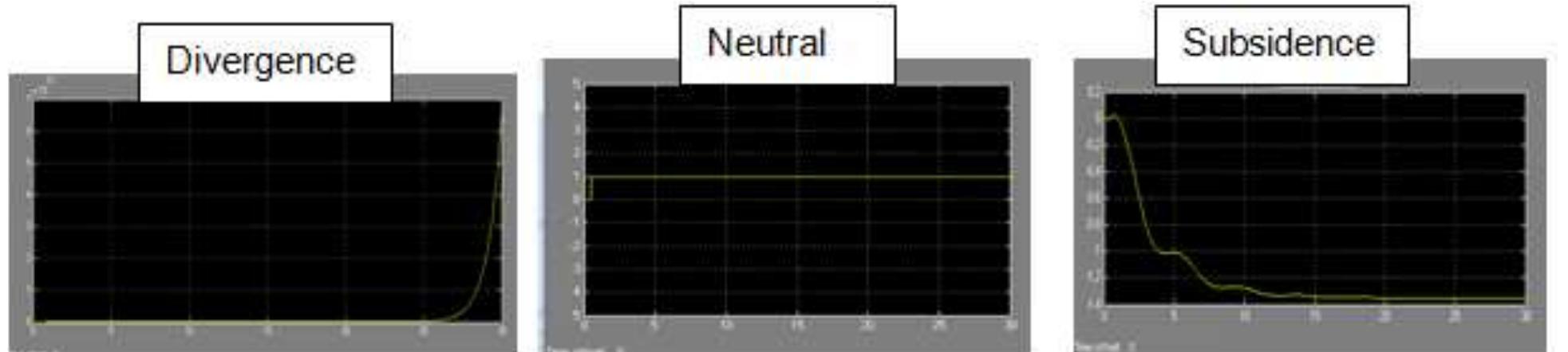
Dynamic stability is the motion of the UAV with respect to time after a disturbance from its
equilibrium position. If the maximum displacement of the UAV from its equilibrium position
decreases with time, then the UAV has positive dynamic stability (Figure 2.2) subsidence
motion). However, if it increases with time then it has negative dynamic stability (Figure 2.2)
divergence motion). Is the motion remain constant with time; the UAV has neutral dynamic
stability.[10]
Figure 2.2 Dynamic stability
2.2.1 UAV Oscillatory motion
The UAV can be statically stable but dynamically unstable. The UAV must be statically stable
to be dynamically stable but static stability does not guarantee dynamic stability.
If the UAV has positive static stability but negative dynamic stability, it will have divergent
oscillation.
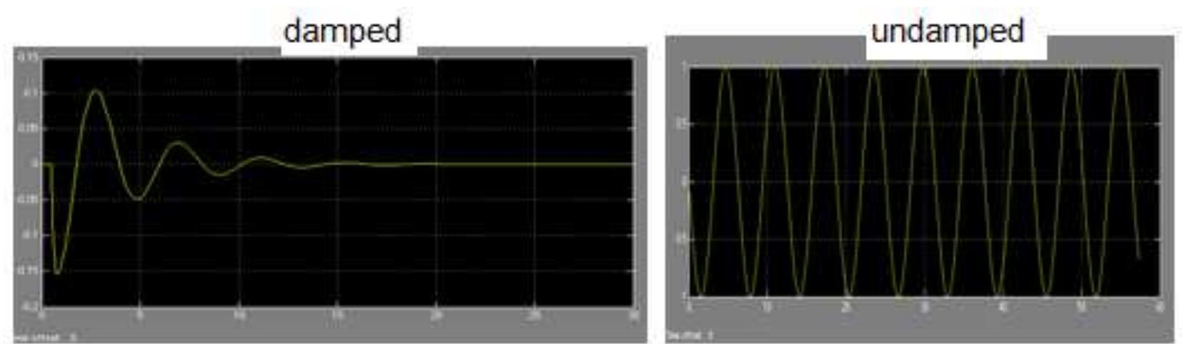
If the UAV has positive static stability but neutral dynamic stability, it will have undamped
oscillation or simple harmonic motion.
The design aim is for the UAV to have both positive and dynamic stability, thus a damped
oscillation. If this condition is mate the UAV will always return to its equilibrium position after
a disturbance.[11]
Figure 2.2.1 Oscillatory motions
Modelling and Simulation of a UH-UAV dynamics 5
�School of Engineering and Technology *BEng Final Year Project Report
2.3 UAV Longitudinal static stability and control
The trim angle of attack is the angle of attack at which the pitching moments are zero.[12]
If a UAV with a negative static longitudinal stability is disturbed from its trim angle of attack, it
will continue to pitch away from the trim angle of attack or equilibrium position. This
characteristic is not desirable. The UAV is said to have neutral static longitudinal stability if
when disturbed from its trim position will remain at the new angle of attack.
The UAV is said to be longitudinally statically stable if a nose-up change in angle of attack
from trim point result in a nose down restoring moment that will return the UAV to its trim
angle of attack or equilibrium position . This is a desirable design characteristic as it results in
the UAV being trimmed at wide range of desired flight speeds.
2.3.1 Contribution of aircraft components to stability
Assuming it is a convectional configuration.
UAV Wings contribution
Aerodynamic centre (AC) is the point at which the change of moment due to change of angle
of attack is zero. It is the point of lift on a wing, Cmα =0. [13]
The wing contribution to the stability is determined by the position of the AC with respect to
the CG position of the UAV. If the CG is forward of the AC, the aircraft will have a natural
nose down pitching tendency that will restore the UAV to its equilibrium position; after an up-
gust disturbance. This is considered to be a stable condition, hence it is desirable. If the CG
is aft of the AC, an up-gust will cause an increase of lift on the AC that will rotate the UAV
about the CG, creating a moment that will rotate the UAV away from the equilibrium position.
This is an unstable condition and hence undesirable.[14]
Therefore the CG must be forward of the AC when designing the UAV. The aerofoils also
contribute to stability. Positive cambered aerofoils cause nose down pitching moment,
whereas negative cambered aerofoils produce nose up pitching moment. Therefore a
negative cambered aerofoil should be chosen for a forward CG. This will ensure stability in
pitch because the natural pitch down tendency will have a nose up counteracting moment due
to the negative camber.
Coefficient of pitching moment due to wing contribution
2.1
[15]
Modelling and Simulation of a UH-UAV dynamics 6
�School of Engineering and Technology *BEng Final Year Project Report
UAV fuselage contribution
In the presence of an up-gust, the fuselage will have a destabilising pitching moment [16]
Coefficient of pitching moment due to fuselage [17]
2.2
K2 –k1 is the body fineness ratio correction factor
S is wing area
c is the wing aerodynamic chord
wf is the average fuselage sections
αow is wing zero lift angle relative to fuselage
if is incidence of the fuselage camber line relative to the fuselage
∆x is fuselage length increment
[18]
UAV engine contribution
If the UAV’s engine axis is at an angle with the free stream; the airflow is turned towards the
engine axis creating a side force on the propeller shaft. For a forward mounted propeller
engine, at positive angles of attack; the force will cause a nose up pitching moment. This will
be destabilising. If the propeller engine is mounted aft of the cg; the upward force will result in
a nose-down pitching moment. This is a stabilising moment. [19]
The engine contributes to Cmα or Cmά. The engine effects can be obtained from wing tunnel
data.
Hence the UAV should have an aft mounted engine.
UAV tail contribution
Assuming a symmetrical aerofoil.
This is a stabilising component of the UAV. It should produce both upward and downward
force when required. For instance, if there is a disturbance due to upward gust; the UAV will
pitch up. An upward force (positive lift) is produced by the tail creating a nose-down restoring
moment. When subjected to an upward-gust the UAV will pitch down. The tail will produce a
down force (negative lift) creating a nose-up restoring moment. The effectiveness of the tail
on stability is determined by its area and the distance from the aft cg to the tail ac. The
positioning of the tail above the wing line is significant considering downwash effects.[20]
Modelling and Simulation of a UH-UAV dynamics 7
�School of Engineering and Technology *BEng Final Year Project Report
Coefficient pitching moment due to tail
2.3
[21]
Downwash angle
2.4
εo is downwash at zero angle of attack
dε/dα is change in downwash with respect to angle of attack
[22]
2.5
CLw is wing lift coefficient (from aerofoil data)
ARw is wing aspect ratio
CLαw is wing lift curve slope
Coefficient of pitching moment of the UAV
Cmo = Cmot+ Cmof+ Cmow
Cmα=Cmαt + Cmαw + Cmαf
UAV Stick free and stick fixed stability
Stick free is when the controls surfaces are free to move and can be displaced from neutral
point when subjected to atmospheric disturbances. This reduces the overall stabilising
surface.
Stick fixed is when the control surfaces are in a fixed position and they are not free to move
when subjected to atmospheric disturbances. This ensures better stability. Hence the UAV
will have stick fixed stability.[23]
At neutral point, Cmα=0
The following equation is used to determine the neutral point
2.6
Modelling and Simulation of a UH-UAV dynamics 8
�School of Engineering and Technology *BEng Final Year Project Report
Desirable geometry configuration
CG forward of the AC.
A negative cambered wing aerofoil.
An aerodynamic balanced tail with symmetrical aerofoil.
An aft mounted engine.
Smaller fuselage area.
Stick fixed stability.
2.4 UAV Longitudinal control
The pitch is controlled by deflection of elevators.
Factors to consider are
1. Hinge moments: These are moments exerted on the control surface
The control surface must overcome the hinge moments. This determines the magnitude of
torque the servo motors must produce, to move the control surface.
Therefore when sizing up the UAV control surfaces, ensure that the servos selected can meet
the control force requirements. However cost of servo motors, size and weight must be also
be considered.
2. Elevator effectiveness: is the measure of how effective the elevator is at producing the
desired pitching moment. [24]
3. Trim: The UAV is trimmed when the forces and moments acting on the UAV are in
equilibrium.
Cm=0 in trim
[25]
2.4.1 Aerodynamic balance
Assuming the centre of gravity is at the most forward position.
Worst case scenario is when the UAV is landing with flaps and landing gear deployed. The
UAV will have a large negative (nose down) pitching moment which has to be counteracted
by the elevator. If the UAV CG is forward of the most estimated forward CG; the UAV will
have to be trimmed at lower angles of attack. This result in increased landing speeds.[26]
The UAV should be designed to have low landing speeds.
Modelling and Simulation of a UH-UAV dynamics 9
�School of Engineering and Technology *BEng Final Year Project Report
2.5 UAV Directional stability
Directional stability is the tendency for the UAV to return to its equilibrium position when
subjected to an atmospheric yaw disturbance.
Assuming the UAV is trimmed at non sideslip flight.
If the UAV return to its equilibrium position (zero sideslip angle) after a yaw displacement,
then it has positive directional stability and if it moves away (increasing sideslip angle) from its
trimmed sideslip, then it has negative directional stability. If the UAV stays at the same
sideslip angle after a yaw displacement, it is considered to have neutral directional
stability.[27] , The UAV must be designed for positive directional stability (Cnβ>0)
2.5.1 UAV components contribution
Fuselage: for the UAV to be directionally stable, the area of the fuselage aft of the CG must
be greater than the fuselage area forward of CG.
2.7
Kn is wing body interference factor
Krl is correction factor
Sfs is the projected area of fuselage
lf is fuselage length
Engine: aft engine is directionally stabilizing
Vertical tail: directionally stabilising
2.8
Dorsal fin: directionally stabilising with reduced drag
Rudder: Fixed rudder increases the vertical area thus increasing directional stability
Wing contribution is Cnβw=CL²/4πAR
[28]
The yawing moment coefficient due to sideslip of the UAV
Cnβ= Cnβf + Cnβw+ Cnβv 2.9
2.6 UAV Directional control
The rudder provides directional control by producing a yaw moment about the CG. The yaw
moment produced is a product of force due to rudder deflection and its distance from the CG.
Its effectiveness is the rate of change of yaw moment with respect to rudder deflection angle.
[29].
The UAV rudder size must be big enough to allow recovery from spin.
Modelling and Simulation of a UH-UAV dynamics 10
�School of Engineering and Technology *BEng Final Year Project Report
2.6.1 UAV Roll stability
Roll static stability is the tendency for the UAV to return to wing level attitude after a lateral
atmospheric disturbance. The condition Clβ<0 must be mate for the UAV to be stable in roll.
[30].
Dihedral: is the angle of span with respect to horizontal axis.
UAV Components contribution
Wing and tail dihedral: stabilising whereas anhedral is destabilising.
Low wing: destabilising in roll due to pendulum effect.
High wing: stabilising in roll due to pendulum effect.
Wing sweep: stabilising assuming sweepback.
Fuselage: stabilising with high wing but destabilising with a low wing.
Vertical tail: produce rolling moment which is stabilising in roll. [31]
Therefore high wing with sweep back is recommendable for a positive roll stable UAV.
2.6.2 UAV Roll control
Roll control is achieved by use of ailerons. These are flap devices which deflect conversely to
each other about the x axis. Their effectiveness is a measure of rate of change of roll moment
due to a change in aileron angle.
2.6.3 UAV coupling motions
Assuming the UAV has been designed following the desired static stability characteristics.
Disturbances in both roll and yaw result in a change in sideslip angle. A change in sideslip
angle also produces moments in roll and yaw. The interaction of these two moments will
result in a coupled motion.
Spiral divergence: This is when a UAV is more stable in yaw than in roll. It is said to have
greater static directional stability than static lateral stability. Therefore a yaw disturbance will
result in a slow sideslip and roll. The dihedral effect is small; hence the UAV will not recover in
roll resulting in an increasingly tightening spiral dive.[32]
Dutch roll: This is an oscillatory motion characterised by coupling of direction and lateral
disturbance. This will result if the UAV dihedral effect is much greater than directional stability.
This motion is heavily damped if the UAV has greater static directional stability. However this
will cause spiral divergence.
“Little spiral divergence is tolerable and preferred to Dutch roll” [33]
Therefore a compromise has to be made when designing the UAV for coupling motion
stability.
Modelling and Simulation of a UH-UAV dynamics 11
�School of Engineering and Technology *BEng Final Year Project Report
3 Aerodynamic Modelling
Equations of motion are required for developing a mathematical model for simulating the UAV
dynamics.
3.1 UAV Moment of inertia
Moment of inertia is body’s resistance to rotation depends on body shape and its mass
distribution.[34]
The mass moment of inertia and products of inertia can either be determined experimentally
or calculated mathematically.
Mathematically calculating moment of inertia
Figure 3.1 Moments of inertia (from Michael. V. Cook Flight dynamics principal 2007 pg
71)
The equations of motion are developed assuming small deviation of UAV motion about the
steady flight condition; also known as “small disturbance theory”. [35]
3.2 Aerodynamic forces and Derivatives
Derivatives are required to simulate and analyse the motions of the UAV. Further
understanding of the derivatives and how they are derived, will enable one to design a UAV
with desired characteristics for its intended mission.
The USAF derivative DATCOM is used for estimating the derivatives.
However the equations for estimating derivatives can be found in Flight stability and
Automatic control second edition by Nelson. Thorough derivative estimation including control
surface derivatives can be found in Flight dynamics principal second edition by Michael V
Cook.
The derivatives will be used to simulate the dynamics of the UAV using a Simulink model.
Modelling and Simulation of a UH-UAV dynamics 12
�School of Engineering and Technology *BEng Final Year Project Report
3.2.1 Longitudinal derivatives
Xu , X w, Zu , Zw, Mw, Mw
, Mq, M
These derivatives are due to u, w, q, disturbances
The forces causing the longitudinal motions are X and Z and the corresponding moment is M.
Aerodynamic derivatives due to forward velocity (u)
Xu: Derivative for the rate of change of axial force with respect to forward speed. Xu is
regarded as a speed damping derivative and it is affected by aerodynamic forces. The
increase in forward speed will result in increase in drag; hence Xu increase with forward
speed.
Zu: Derivative for rate of change of normal force with respect to forward speed. Increasing
forward speed will result in increase in lift, thus decrease in Zu.
Mu: Derivative for change in pitching moment with due to forward speed. Mu=0 If
compressibility and aeroelastic effects are ignored.
Aerodynamic derivatives due to normal velocity (w)
Xw: Derivative for change in axial force due to change in normal velocity. Xw is affected by
increase in drag.
Zw: Derivative for change in normal force due to change in normal velocity. Zw is affected by
increase in lift coefficient.
Mw: Derivative for change in pitching moment due to change in normal velocity. Mw shows
the longitudinal static stability of the UAV with respect to change of incidence angle. For
longitudinal static stability Mw<0
Aerodynamic derivatives due to pitch rate (q)
These are tail contributions
Xq: Derivative for change in axial force due to change in pitch rate.
Zq: Derivative for change in normal force due to change in pitch rate.
Mq: Derivative for change in pitching moment due to change in pitch rate.
Aerodynamic derivatives due to elevator deflection
Xη: Derivative for change in axil force due to elevator deflection.
Zη: Derivative for change in normal force due to elevator deflection. Zη is a measure of
elevator effective ness at producing down force or lift.
Mη: Derivative for change in pitching moment due to elevator deflection. Mη is a measure of
elevator effectiveness on producing pitch about the UAV CG.
[36] (Aerospace systems dynamics and control notes)
Modelling and Simulation of a UH-UAV dynamics 13
�School of Engineering and Technology *BEng Final Year Project Report
Assumptions
Thrust variations are neglected.
Compressibility effects are neglected.
Aerodynamic effects are neglected.
Drag effects are ignored.
Subsonic flight.
Incidence angle is very small.
Effects of elevator deflection are ignored.
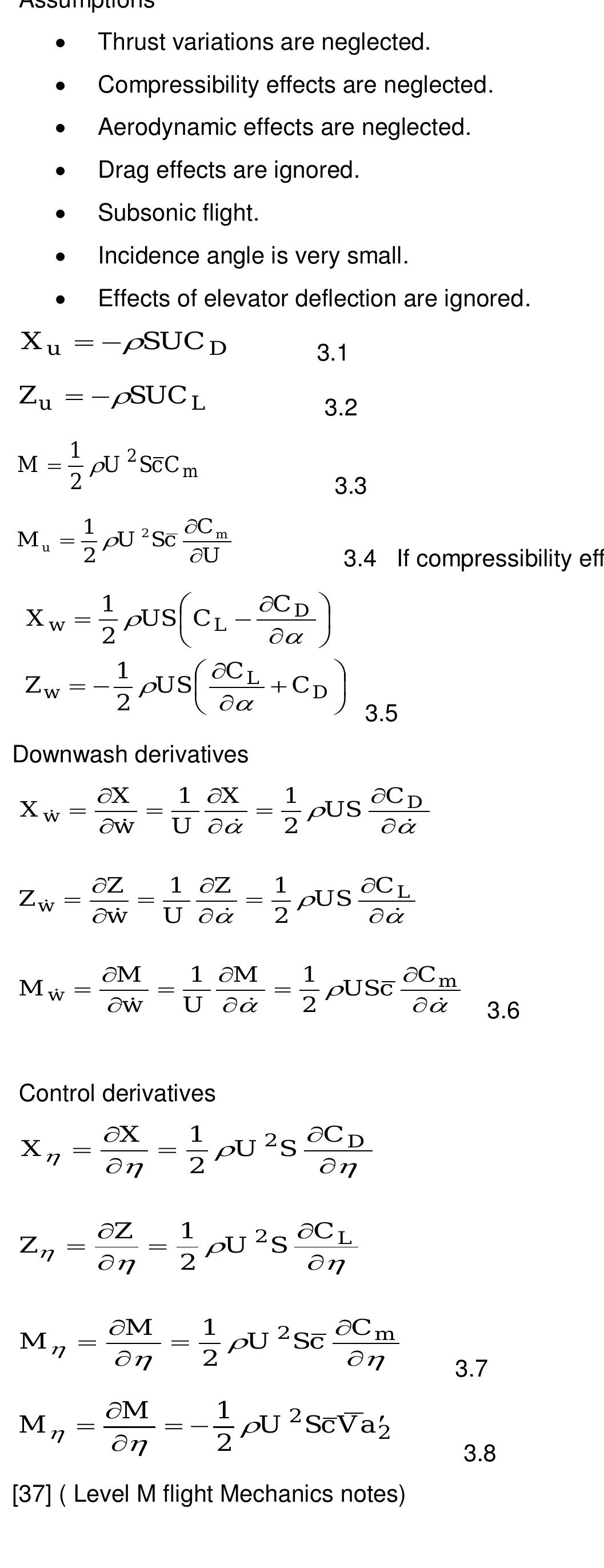
X u SUC D 3.1
Z u SUC L 3.2
1
M U 2 Sc C m
2 3.3
1 C m
Mu U 2 Sc
2 U 3.4 If compressibility effects are not ignored
1 C D
Xw US C L
2
1 C L
Zw US CD
2 3.5
Downwash derivatives
X 1 X 1 C D
Xw US
w
U 2
Z 1 Z 1 C L
Zw US
w
U 2
M 1 M 1 Cm
Mw USc
w
U 2 3.6
Control derivatives
X 1 C D
X U 2 S
2
Z 1 C L
Z U 2 S
2
M 1 Cm
M U 2 Sc
2 3.7
M 1
M U 2 Sc V a2
2 3.8
[37] ( Level M flight Mechanics notes)
Modelling and Simulation of a UH-UAV dynamics 14
�School of Engineering and Technology *BEng Final Year Project Report
Tail volume coefficients
3.9
3.10
Normal axis derivatives
Normal force derivatives due to change in forward velocity, downwash, normal velocity, pitch
rate and elevator deflection, respectively.
3.11
[38]
Pitching moment derivatives
3.12
[39]
3.2.2 The Lateral Derivatives
Yv , Lv , Lp , L , Nv , Np, Nr , N
These derivatives are due to v, p, r, and disturbances
The force causing the lateral motions is Y and the corresponding moments are L and N
Lateral derivatives due to sideslip velocity (v)
Yv: Derivative for change in lateral force due to change in sideslip velocity.
Nv: Derivative for change in yawing moment due to change in sideslip velocity. Nv contribute
to directional static stability. Nv >0 for a directionally stable UAV.
Lv: Derivative for change in rolling moment due to change in sideslip velocity. Lv is important
for roll stability. Lv< 0 for a roll stable UAV.
[40]
Modelling and Simulation of a UH-UAV dynamics 15
�School of Engineering and Technology *BEng Final Year Project Report
Lateral derivatives due to roll rate (p)
Yp: Derivative for change in lateral force due to change in roll rate.
Lp: Derivative for change in rolling moment due to rate of roll rate. Lp depends on wing area
and size of tail surfaces.
Np: Derivative for change in yawing moment due to rate of roll rate. Wing is the main
contributor to Np.
[41]
Lateral derivatives due to yaw rate (r)
Yr: Derivative for change in lateral force due to yaw rate.
Nr: Derivative for change in yawing moment due to yaw rate. Nr is a yaw damping derivative.
It is negative.
Lr: Derivative for change in rolling moment due to roll rate. Lr is positive.
Lateral derivatives due to aileron deflection
Yξ: Derivative for change in lateral force due to change in aileron deflection.
Lξ: Derivative for change in rolling moment due to change in aileron deflection. L ξ is a
measure of aileron effectiveness.
Nξ: Derivative for change in yawing moment due to aileron deflection.
[Aerospace systems dynamics and control notes]
Lateral derivatives due to rudder deflection
Yζ: Derivative for change in lateral force due to rudder deflection.
Lζ: Derivative for change in rolling moment due to rudder deflection.
Nζ: Derivative for change in yawing moment due to rudder deflection. Nζ is a measure of
rudder effectiveness.
[42]
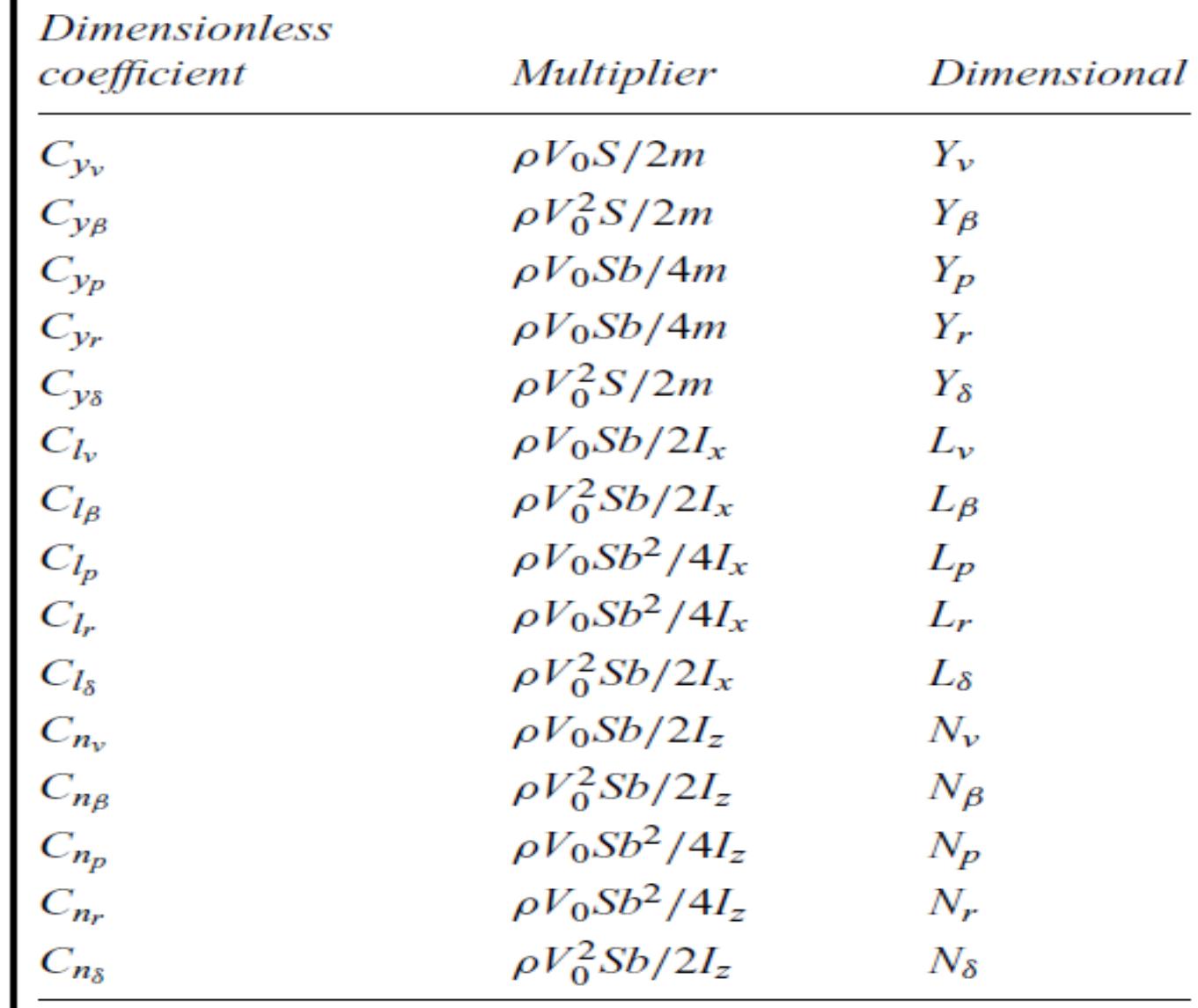
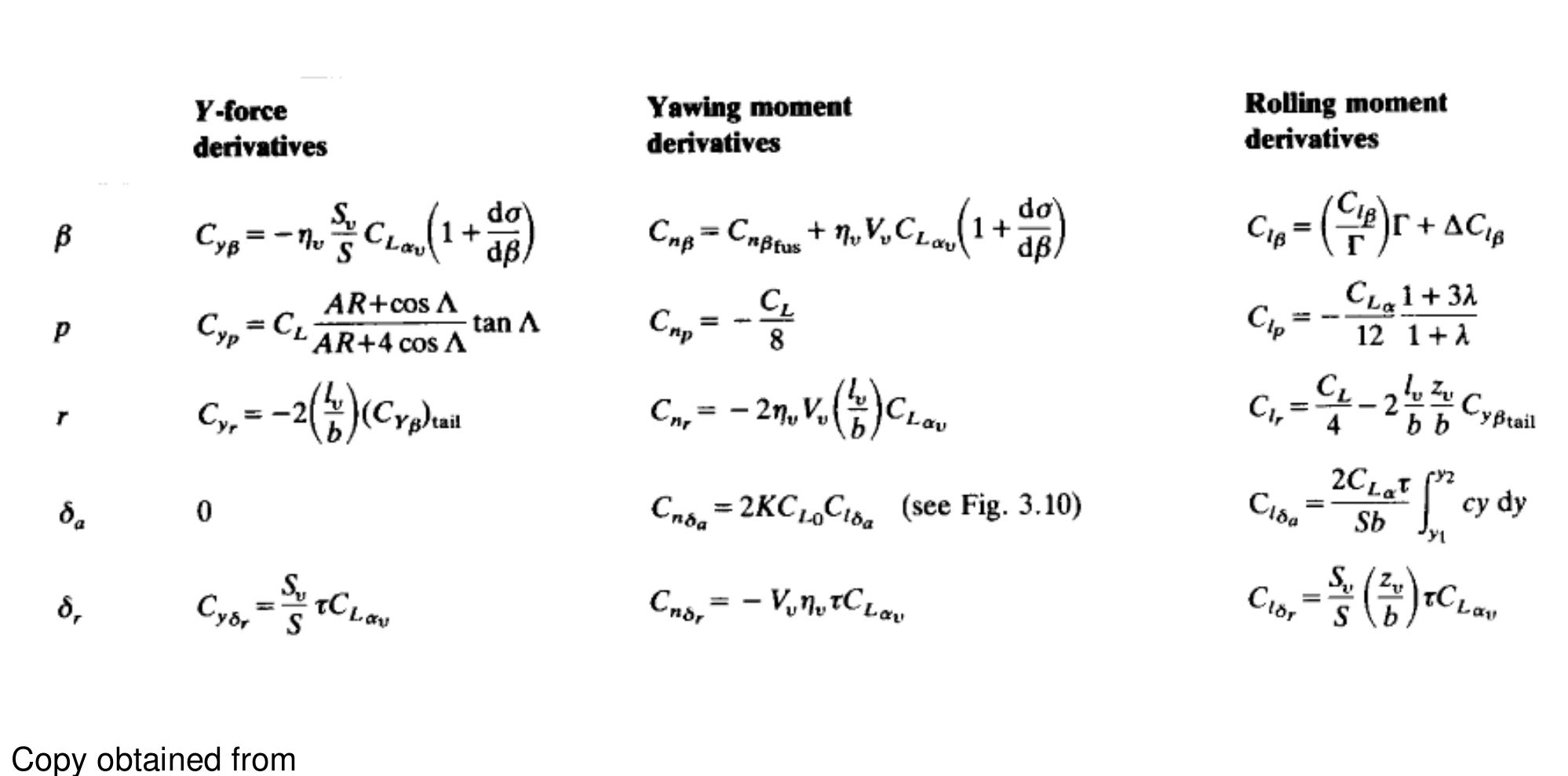
Rolling moment derivatives due to sideslip, roll rate, yaw rate and aileron deflection,
respectively.
3.14
Modelling and Simulation of a UH-UAV dynamics 16
�School of Engineering and Technology *BEng Final Year Project Report
Yawing moment derivatives due to sideslip, roll rate, yaw rate and rudder deflection,
respectively
3.15
[43]
Lateral force derivatives due to sideslip, roll rate, yaw rate and rudder deflection
3.16
3.17
3.18
[44]
4 UAV Longitudinal motions
Assuming stick fixed
The longitudinal motions to be analysed is the short pitching period oscillation (SPPO) and
the phugoid motion. SPPO is a highly damped motion characterised by change in incidence
angle and pitch angle in phase at constant forward speed. Assuming u=0
[45], (Introduction to aircraft stability and control 2 ASE4 notes studynet )
Estimating UAV SPPO
4.1
[46]
Mq is the derivative for pitching moment due to pitch rate
Mα,Mά are the derivative for pitching moment due to change in incidence
Zα is the derivative for change in normal force due to incidence
Uo is change in forward speed
Modelling and Simulation of a UH-UAV dynamics 17
�School of Engineering and Technology *BEng Final Year Project Report
4.2
Period = 2π/ω
t1/2= -ln2/(-ζωn) time to half amplitude
N1/2 = (t1/2)/Period, number of cycles
Phugoid
Phugoid is the lightly damped oscillation with a long period. It is characterised by change in
pitch attitude angle with very small changes in incidence. The change in forward speed is out
of phase with pitch attitude angle by 90°. [47], (Introduction to aircraft stability and control 2
ASE4 notes studynet )
Estimating UAV phugoid
4.3
Xu and Zu are derivatives due to forward speed
Uo is the forward speed
g is the acceleration due to gravity
Estimation of phugoid
4.4
Period = 2π/ω
t1/2= -ln2/(-ζωn) , time to half amplitude
N1/2 = (t1/2)/Period, number of cycles
[48]
4.1 Derivative influence on longitudinal motion
The characteristic equations show clearly the influence of derivatives to the longitudinal
motion.
If the damping ratio and the frequency of the SPPO motion is high; the UAV will have a faster
response to elevator input without overshoot. However if the UAV has lightly damped motion
with low frequency, the UAV will be difficult to control. [49]
Influence of stability derivatives of longitudinal motions
Mq and Mά these are SPPO damping derivatives . Increasing Mq and Mά increases the
damping of the SSPO motion.
Mα is the SPPO frequency derivative. Increasing Mα increases the frequency of the SPPO
motion.
Xu is the damping derivative for phugoid motion. Increasing Xu increases the damping ratio of
the phugoid motion.
Modelling and Simulation of a UH-UAV dynamics 18
�School of Engineering and Technology *BEng Final Year Project Report
Zu is the derivative for the frequency of the phugoid motion. Increasing Zu increases
frequency of the phugoid motion.
The UAV should be easy to control therefore it should be designed to have heavily damped
motions with high frequency. Therefore the Mα, Mά and Mq derivatives should be large. [50]
5 UAV Lateral motion
Assuming stick fixed
The lateral motions to be simulated and analysed are Directional divergence, Spiral
divergence and Dutch roll oscillation. These are characterised by a combination of rolling,
yawing and sideslip motions. [51]
Roll mode
Heavily damped none oscillatory motion.
A roll disturbance will cause an up-going wing to decrease in lift while the down-going wing
increases in lift. This develops a restoring rolling moment that damps out the motion. However
the UAV does not return to its original position. [52], (Introduction to aircraft stability and
control 2 ASE4 notes studynet )
Estimating UAV roll mode
Characteristic equation
5.1
τ is roll time constant.
ζr = Lp
t1/2 = -ln2/Lp
Spiral
A side slip disturbance will cause a yawing moment due to fin, this will result a yawing motion
which develops a rolling moment. The rolling moment then causes an increase in sideslip
velocity. [53], (Introduction to aircraft stability and control 2 ASE4 notes studynet)
Estimating UAV spiral mode.
Assuming the derivatives has the usual signs. That is ignoring control reversal.
The characteristic equation
5.2
The condition for stable spiral mode
5.3
[54]
Modelling and Simulation of a UH-UAV dynamics 19
�School of Engineering and Technology *BEng Final Year Project Report
Dutch roll mode
An oscillatory motion resulting from a disturbance in yaw, there is a restoring yawing moment
and damping force due to fin. This is a very undesirable motion.
Estimating UAV Dutch roll mode
5.4
Characteristic equation
5.5
Damping and frequency for the Dutch roll motion
5.6
Period = 2π/ω 5.7
t1/2= -ln2/(-ζωn) time to half amplitude 5.8
N1/2 = (t1/2)/Period, number of cycles 5.9
[55]
6 Models and Simulations
Matlab and Simulink is a technical computing language which was used to model the UAV
and simulate its dynamics.
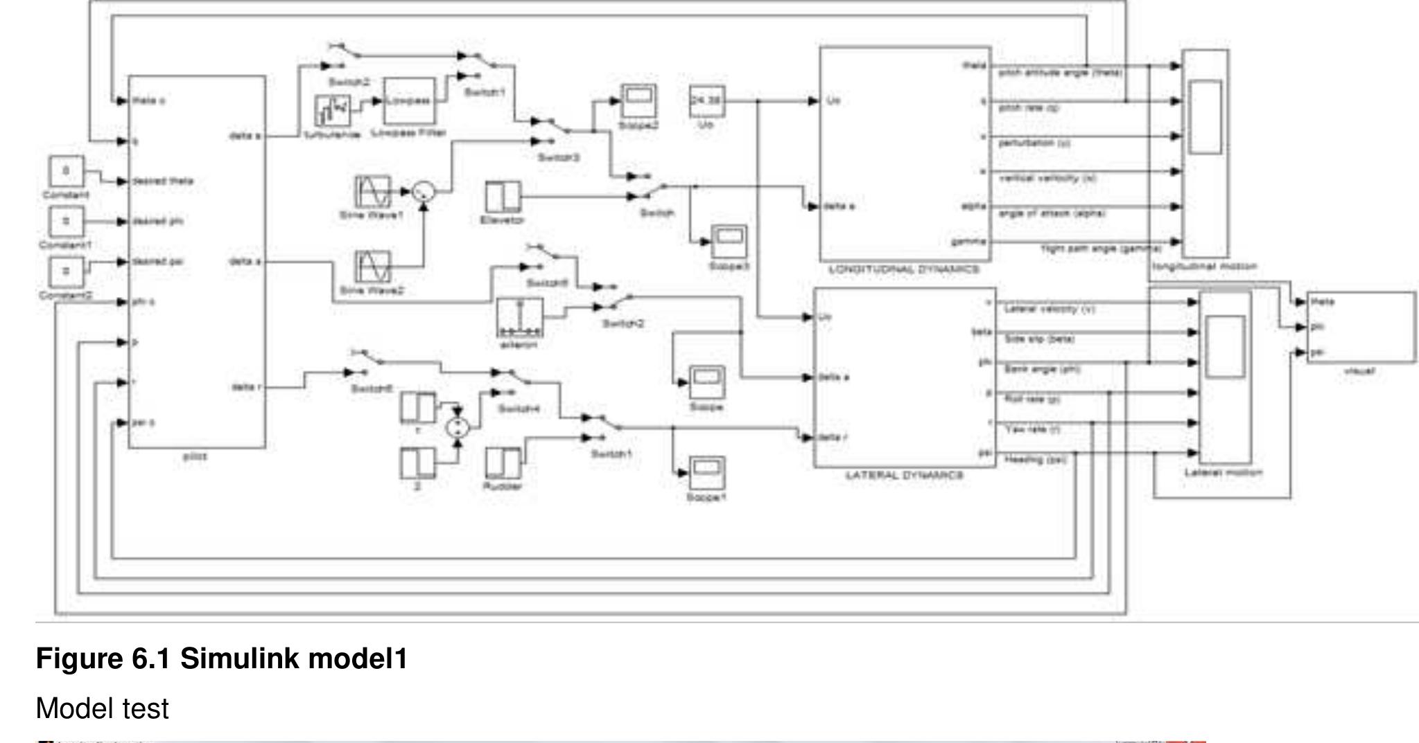
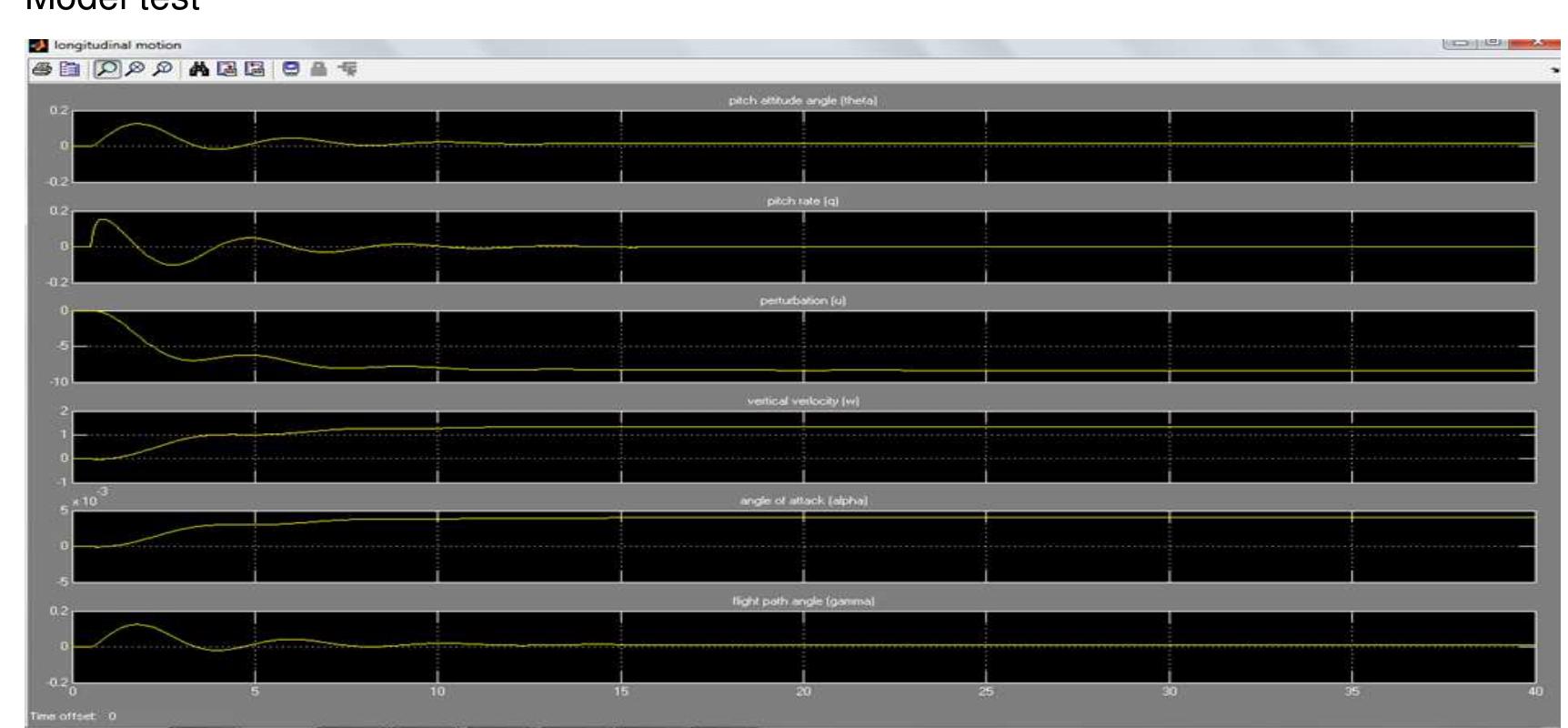
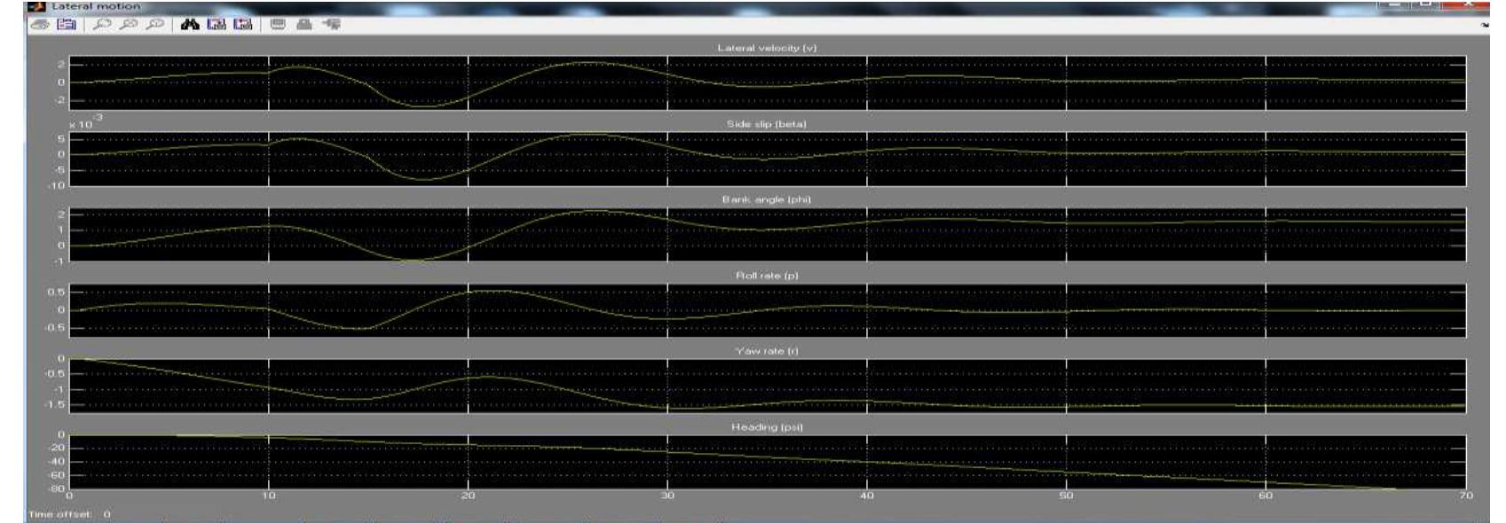
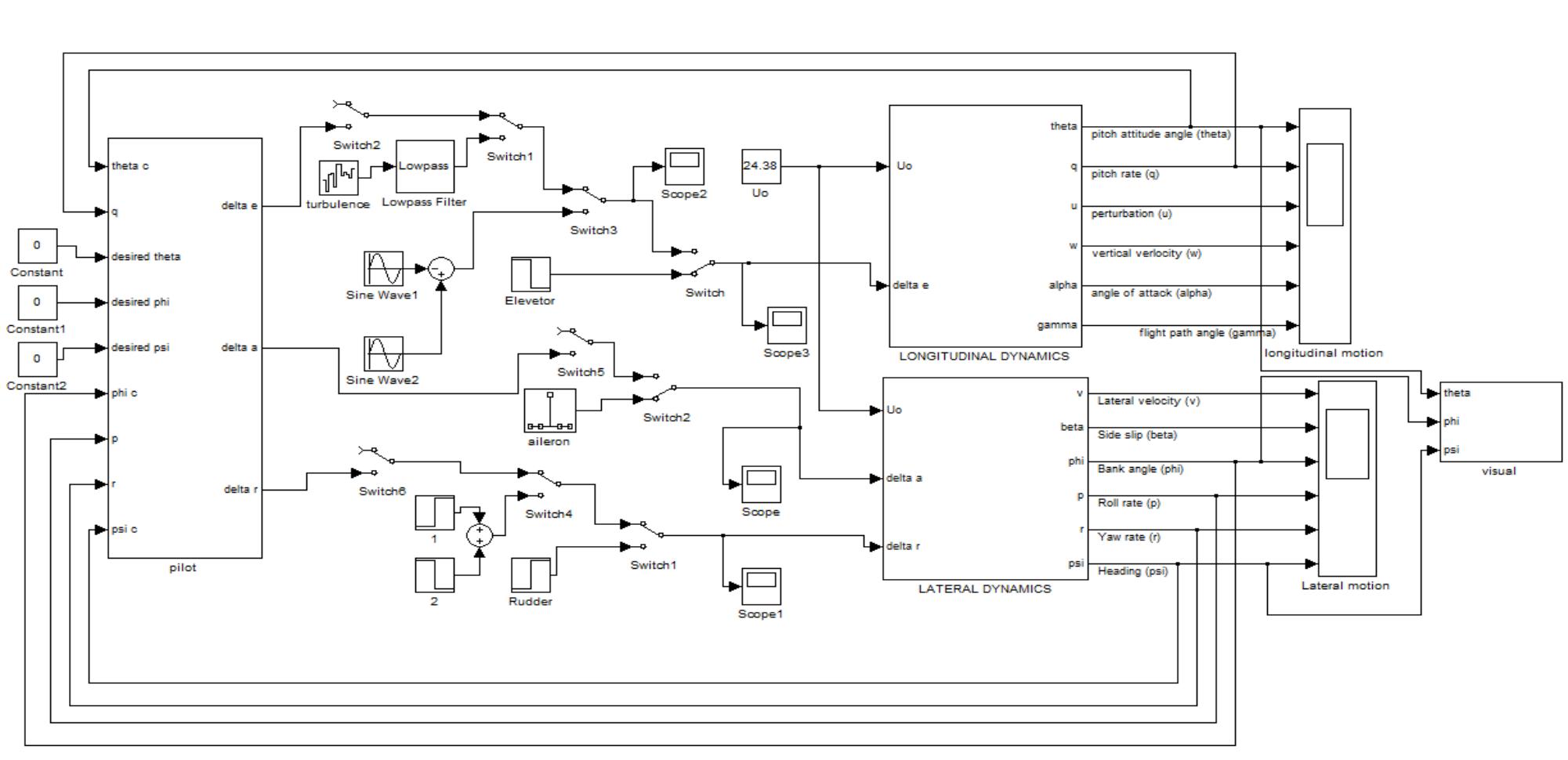
A generic Simulink model was created to simulate the UAV dynamics. The model was then
tested using the Navion aircraft derivatives. The Navion aircraft was used because a lot of
simulation results and its dynamics characteristics are readily available. The data is available
online and in textbooks such as Flight stability and Automatic control by Robert C Nelson.
The derivatives were computed to determine the forces and moments. The inputs to the
model were the control surfaces and the atmospheric disturbances. The outputs of the model
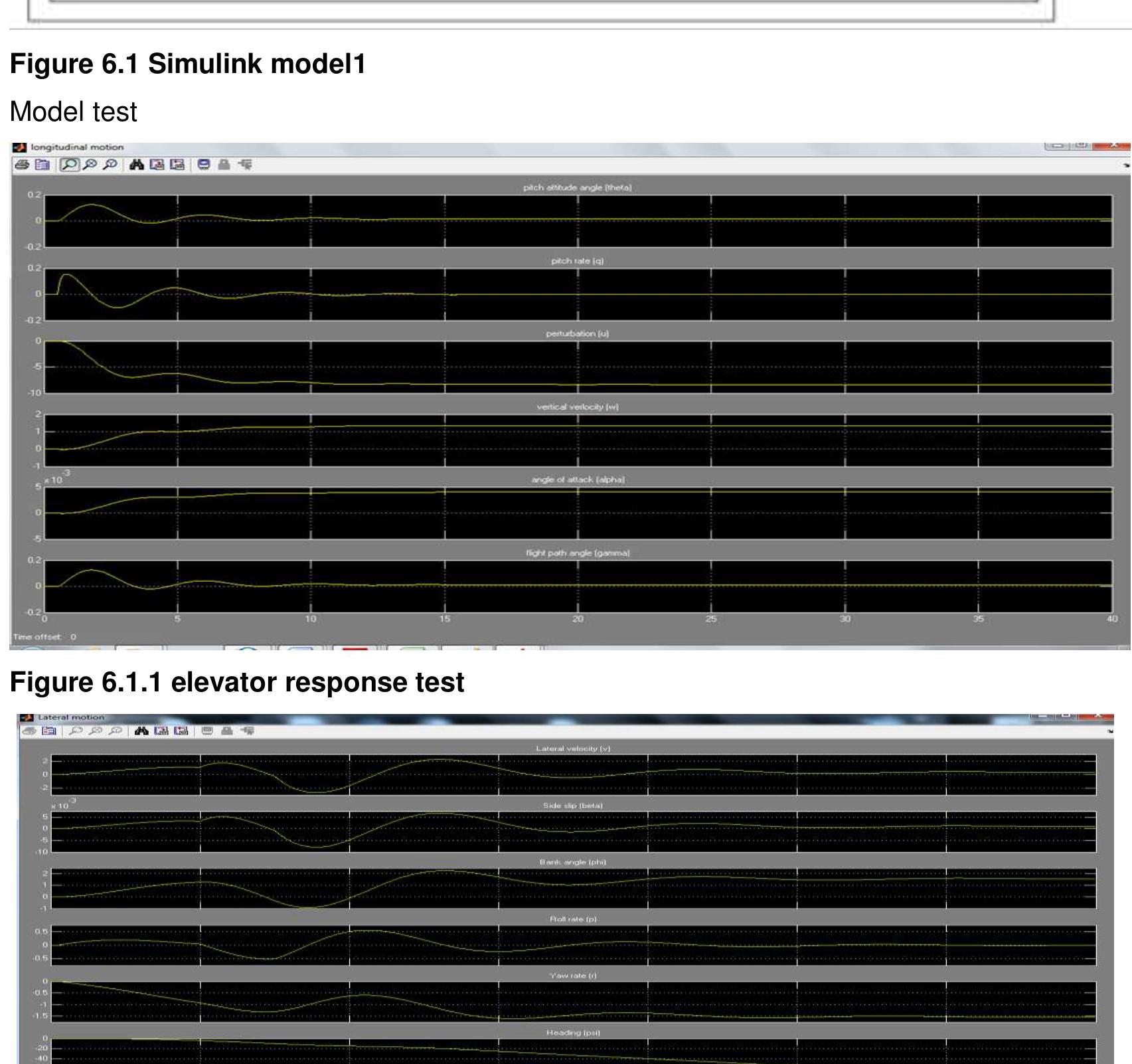
were the angles and rates; [Figure 6.1.1]. The model has a visual platform with Matlab based
animation and flight gear interface using UDP protocol. The autopilot block provides a
platform for flight augmentation, if required.
The derivatives are specific for the specified flight condition. That is speed and altitude.
Therefore the simulation can only be run for a single flight speed. Each time the flight
condition changes the whole derivatives would have to be calculated again. The wind gust
and wind shear magnitude and direction cannot be specified accurately. These are some of
the major drawbacks of the model. Hence an alternative model had to be developed.
Modelling and Simulation of a UH-UAV dynamics 20
�School of Engineering and Technology *BEng Final Year Project Report
6.1 The UAV generic model 1
Figure 6.1 Simulink model1
Model test
Figure 6.1.1 elevator response test
Figure 6.1.2 rudder response test
Modelling and Simulation of a UH-UAV dynamics 21
�School of Engineering and Technology *BEng Final Year Project Report
6.2 UAV generic model 2
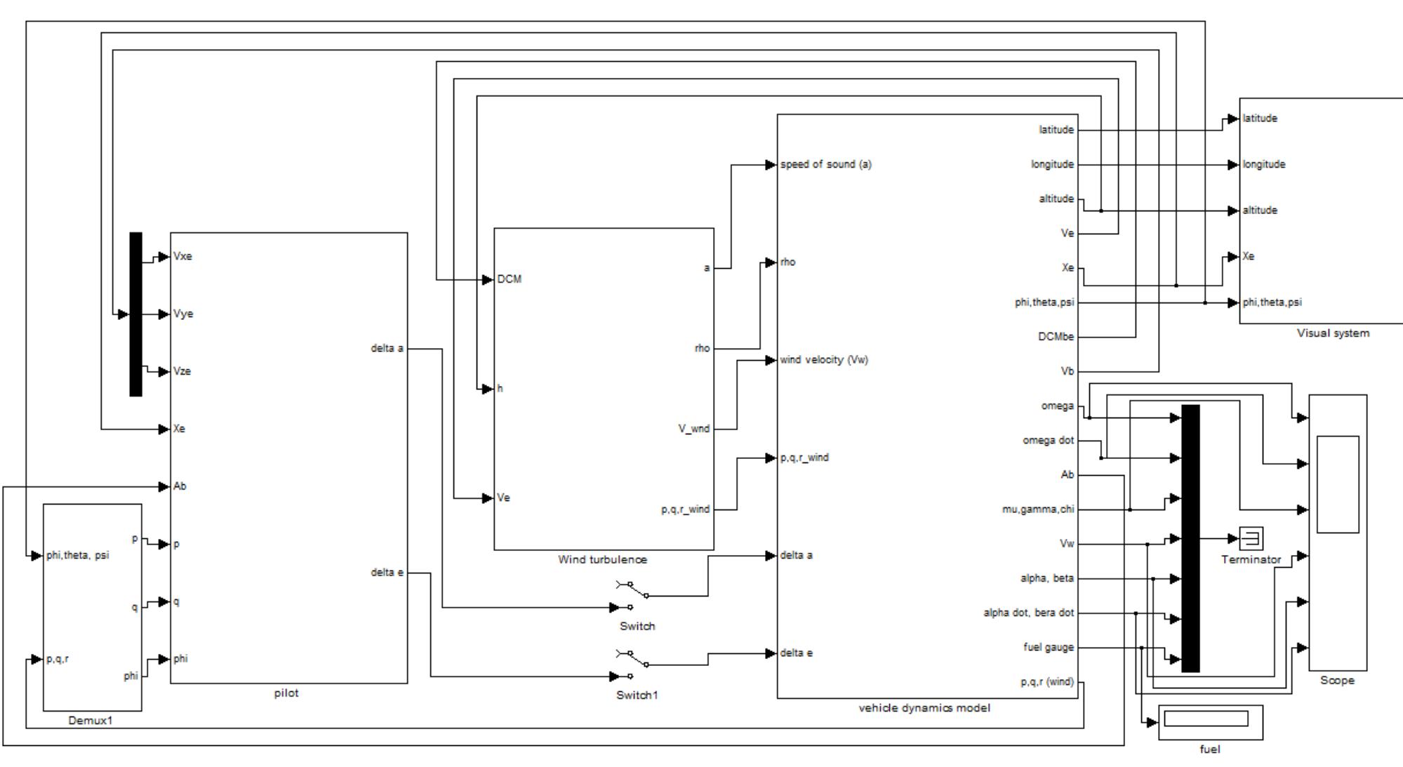
Further work was done to develop a model that can simulate the whole flight profile. The
model does not require change of derivatives. This is achieved by use of digital datcom. The
datcom is linked to the Simulink model and it estimates the derivatives at different altitudes
and flight speeds based on the UAV geometry. The model has a wind shear, turbulence and
gust platform, where the wind speed and direction can be changed to analyse its effects on
the UAV. The models combine both wind and body axis system. There is a visual platform for
Matlab based animation, flight path data and an interface with flight gear. This enables the
user to visually analyse the dynamics of the UAV. The model also has a flight augmentation
platform for when it is required. The models also have extra benefits such as mission profile
analysis, endurance test, testing what is and not possible for the UAV in terms of extreme
bank angle, turn rate, etc depending on the speeds.
The digital datcom is usually programmed in FORTRAN language. It takes time to understand
how it works and need someone who really knows the program. Errors in the dtacom
program might go unnoticed and this further limits the reliability of the model as a whole;
hence a major drawback. However the benefits outweigh the drawbacks hence the model can
be used for UAV dynamics analyses. A solution for both model 1 and model 2 drawbacks
was required. A general solution to all drawbacks of both models was developed.
Generic model 2
Figure 6.2 Simulink model 2
This was the solution to drawbacks highlighted in model1
Modelling and Simulation of a UH-UAV dynamics 22
�School of Engineering and Technology *BEng Final Year Project Report
6.3 UAV generic model 3
The solution was as a result of the group members not providing data required for the
simulation. The wind tunnel test had not been carried out and the computational fluid
dynamics analyses (CFD) was not completed. The structural designer was not providing the
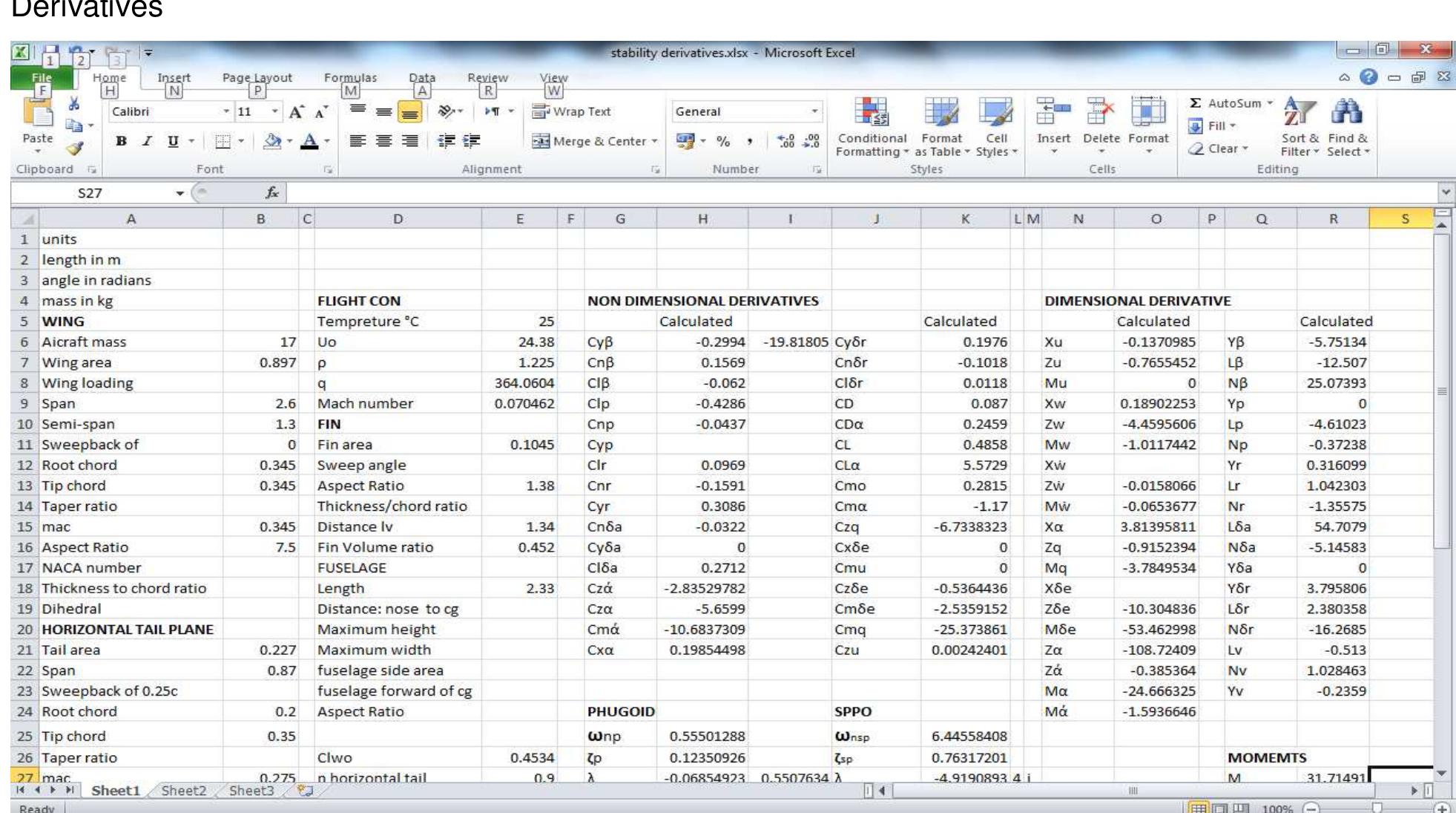
values required to estimate the derivatives. Therefore a solution was to use an excel file that
calculates all the derivatives based on the geometry and flight condition. The data from the
wind tunnel and CFD would be entered once available. The file estimates all the required
derivatives for an accurate analysis of the dynamics. It also estimates the frequency and
damping for spiral mode, dutch roll mode, roll mode, pure yaw motion, SPPO and phugoid.
The model also estimates X,Y,Z forces and the M,N,L moments. The longitudinal and lateral
transfer functions and Eigen vectors for wind shear and motions can be obtained from the
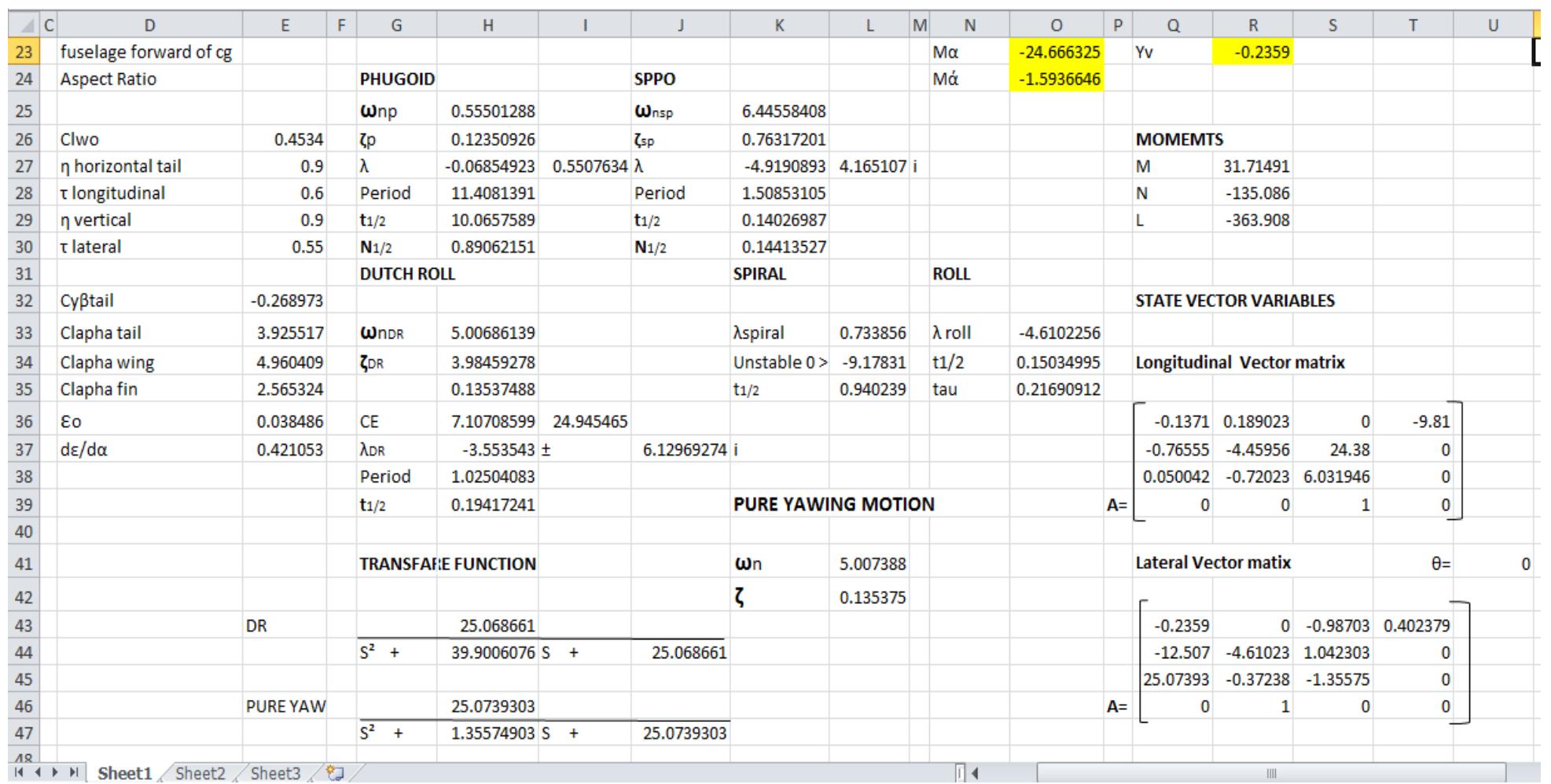
model3, [Figure 6.3.3]. When the speed is changed the derivatives, motions, forces and
moments automatically updates. This saves time by not having to recalculate all the
derivatives each time the flight condition changes, [Figure 6.3.1].
This model offers far more benefits with potential for further development. Effects of changing
the UAV geometry on motions can be analysed. This allows flexibility on testing various
geometries and finding the most suitable UAV geometry for the intended mission.
Mathworks has interfaced with Microsoft applications. Therefore lookup Simulink function
blocks can be used to directly source data from the excel model. This solves the Simulink
model 1 drawback because changing speed or geometry of the UAV in excel file will
automatically updates the Simulink model 1. The excel model will allow the Simulink model 1
to be flexible and saves a lot of time. Linking Simulink model1 and excel model will increase
chances of failure in Simulink model 1 but it’s a minor drawback considering the benefits.
The excel file is easy to update; it does not require much knowledge to change geometry
values and input new UAV model. This saves time and also the estimates for motions, forces
and moments can be compared to the outputs of Simulink model 2; thus solving the model 2
drawbacks.
The excel model can further be developed to include irritation functions. This allows the
designer to choose the frequency and damping of the motions and the model will output a
suggested geometry by changing tail area, wing area, chord, span, tail position from cg,
dihedral angle etc.
The equations used for the model calculations are listed in Appendices.
Modelling and Simulation of a UH-UAV dynamics 23
�School of Engineering and Technology *BEng Final Year Project Report
UAV model 3
Derivatives
Figure 6.3.1 Excel model
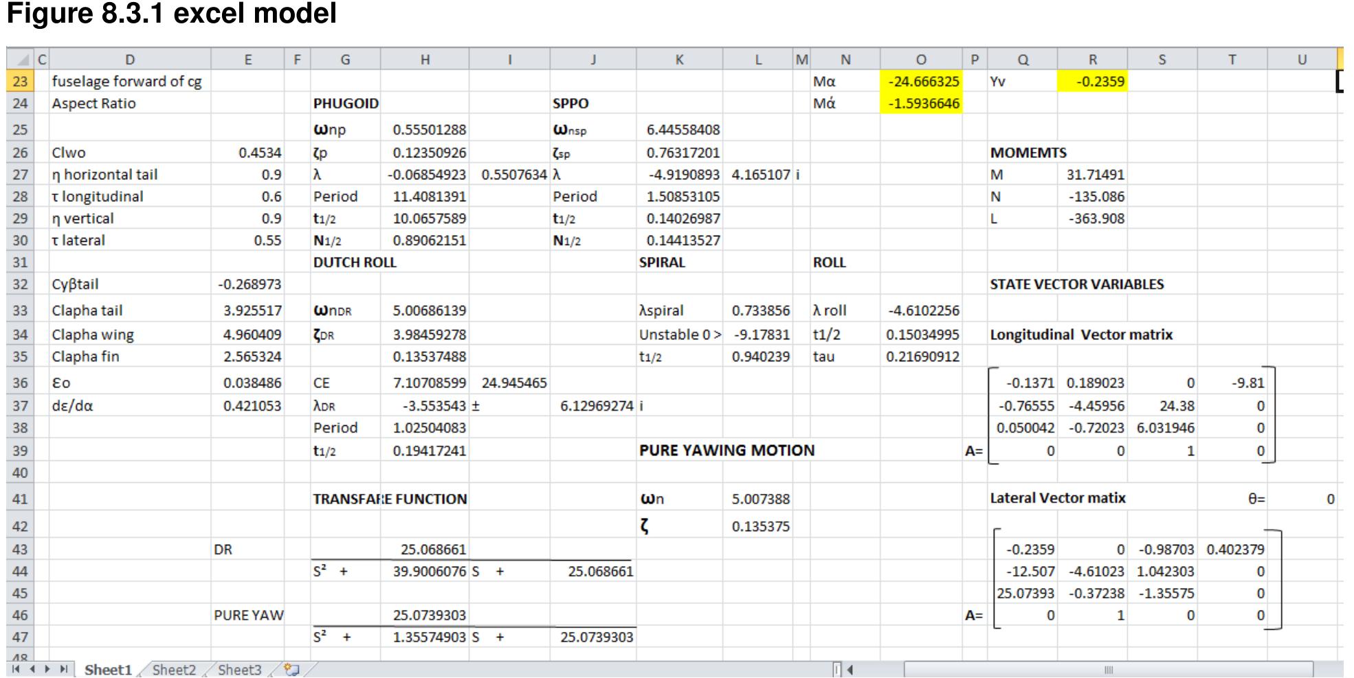
Motion and forces , Eigen vectors and transfer functions
Figure 6.3.2 Excel model
Modelling and Simulation of a UH-UAV dynamics 24
�School of Engineering and Technology *BEng Final Year Project Report
7 Results
MAK II is a UH UAV.
MAK II geometry was used for the simulation.
The damping ratio (ζ) and the undamped frequency (ω) was calculated using the excel model.
Time period, time to half amplitude and the number of cycles was also determined using the
excel model. This was then used to validate the Simulink model.
7.1 Longitudinal dynamics
The long term (phugoid) and short term (SPPO) dynamics of step elevator input
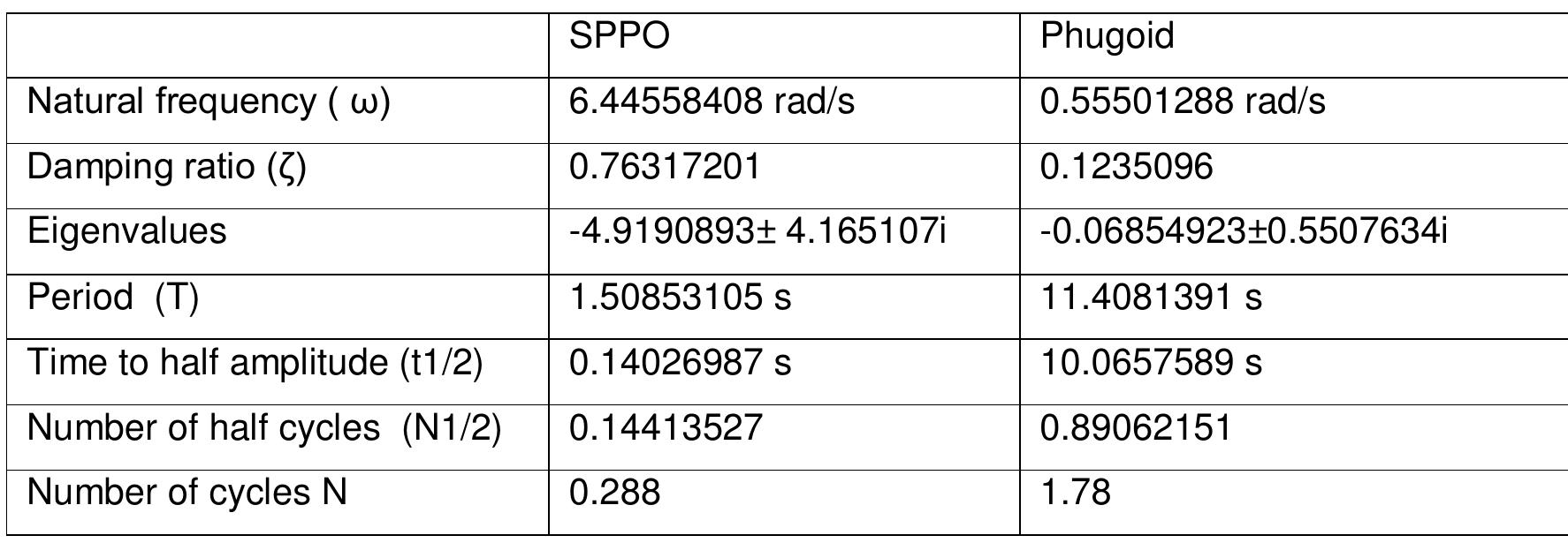
Table 1 Longitudinal motion
SPPO Phugoid
Natural frequency ( ω) 6.44558408 rad/s 0.55501288 rad/s
Damping ratio (ζ) 0.76317201 0.1235096
Eigenvalues -4.9190893± 4.165107i -0.06854923±0.5507634i
Period (T) 1.50853105 s 11.4081391 s
Time to half amplitude (t1/2) 0.14026987 s 10.0657589 s
Number of half cycles (N1/2) 0.14413527 0.89062151
Number of cycles N 0.288 1.78
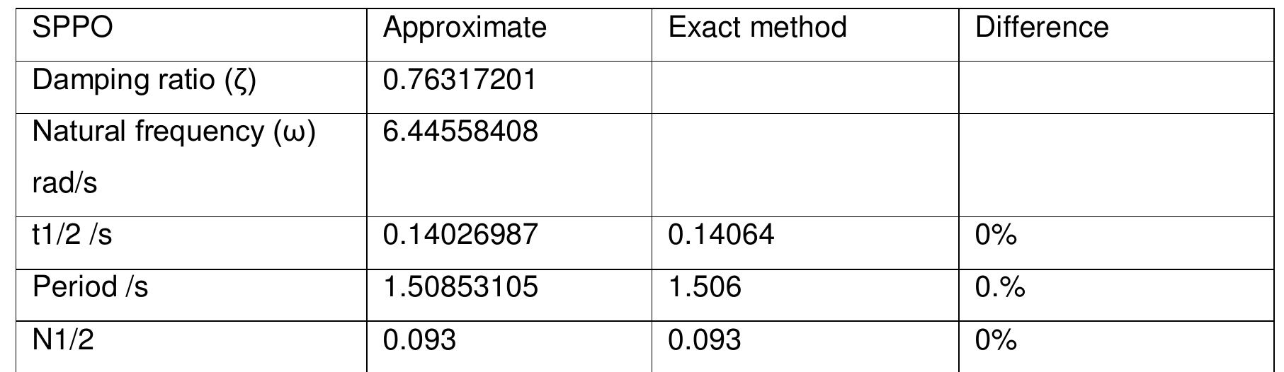
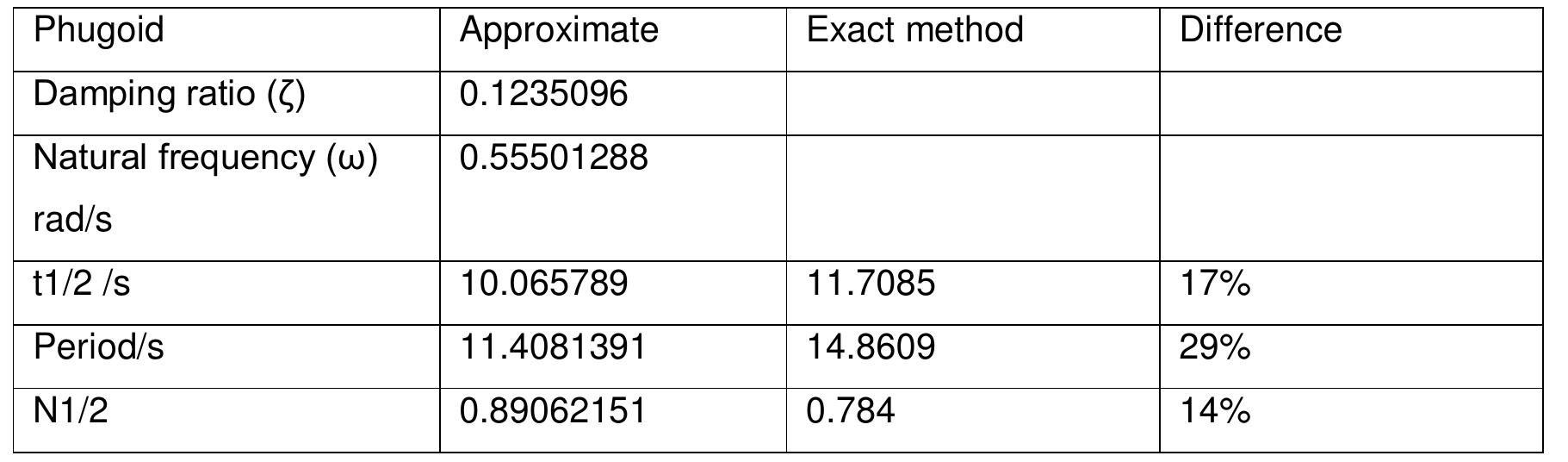
The table above shows that the phugoid motion damps half of its initial amplitude in
approximately 10 seconds. The phugoid motion lasted around 2 cycles. The SPPO motion
lasted for 0.3 cycles.
Modelling and Simulation of a UH-UAV dynamics 25
�School of Engineering and Technology *BEng Final Year Project Report
Long-term response Simulink model
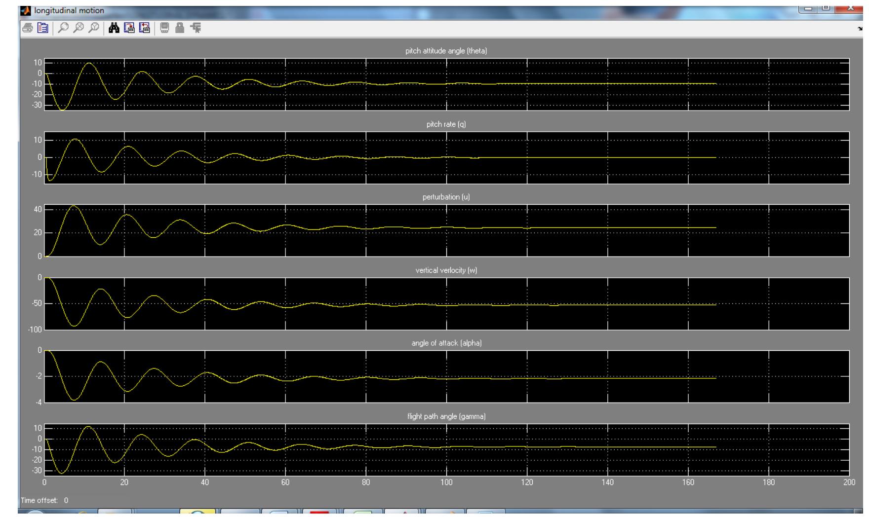
Figure 7.1.1 Long term response to elevator step input
The figure above shows that the UAV returns to equilibrium position in approximately 80
seconds after an elevator step input disturbance. This shows that the UAV longitudinal
dynamics are stable. The pitch rate (q) returns to zero steady state from a maximum pitch
rate of 9°/s. The angle of attack (α) has decreased by 2° due to the influence of SPPO mode.
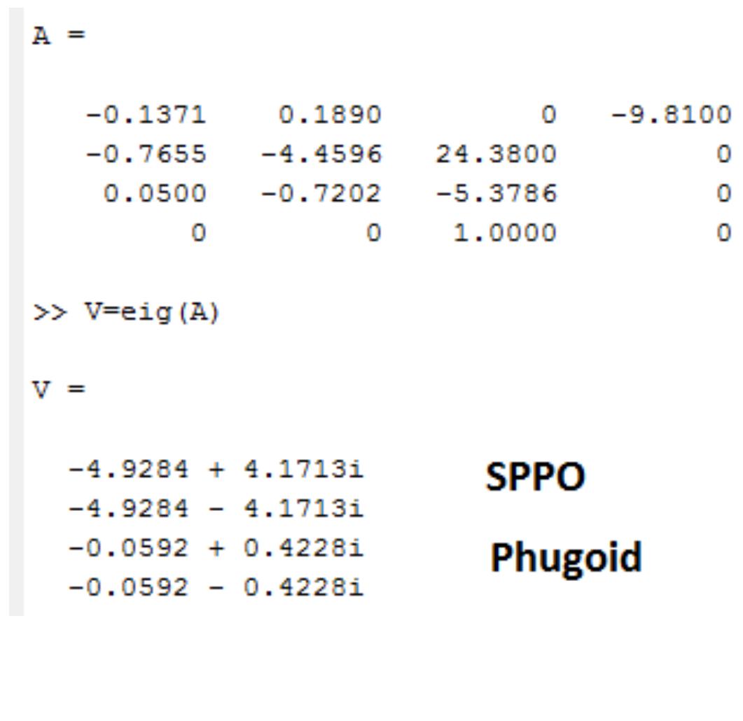
The excel model was used to obtain an Eigen vector. The Eigen vector was then solved in
Matlab to obtain the Eigen values.
Modelling and Simulation of a UH-UAV dynamics 26
�School of Engineering and Technology *BEng Final Year Project Report
Table 2 SPPO comparison
SPPO Approximate Exact method Difference
Damping ratio (ζ) 0.76317201
Natural frequency (ω) 6.44558408
rad/s
t1/2 /s 0.14026987 0.14064 0%
Period /s 1.50853105 1.506 0.%
N1/2 0.093 0.093 0%
Table 3 phugoid comparison
Phugoid Approximate Exact method Difference
Damping ratio (ζ) 0.1235096
Natural frequency (ω) 0.55501288
rad/s
t1/2 /s 10.065789 11.7085 17%
Period/s 11.4081391 14.8609 29%
N1/2 0.89062151 0.784 14%
7.2 UAV responds to Gust and turbulence
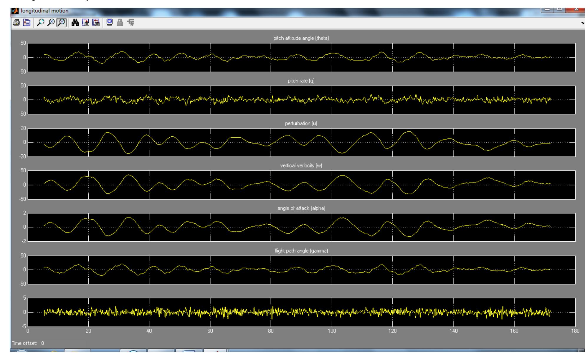
Turbulence is a chaotic system. It’s not liner and cannot be mathematically predicted.
Therefore noise generator was used to generate the turbulence and a low pass filter to
determine the amplitude of the turbulence. Sine waves can be used to characterise sinusoidal
gust. The turbulence was assumed to be a stationary phase that the UAV flies through. The
effects of the turbulence on the UAV dynamics are increased by increasing the turbulence
speed and amplitude. The UAV was subjected to various turbulent profiles and it exhibited
positive dynamic stability characteristics, [Figure 7.2]. The wind shear vector can be obtained
from the excel model, [APPENDIX C]. The effects of wind shear to the longitudinal model can
then be analysed based on the Civil Aviation Organisation (ICAO) standards. [56]
The knowledge of UAV’s response to wind shear and turbulence is useful when setting the
limiting flight conditions at which the UAV can be flown. Avoiding extreme flight conditions
may result in reduced maintenance cost and longer life cycle for the UAV.
Modelling and Simulation of a UH-UAV dynamics 27
�School of Engineering and Technology *BEng Final Year Project Report
Long-term response to turbulence
Figure 7.2 response to turbulence
7.3 Lateral Dynamics
The excel model was used to estimate the lateral motions. These were then used to validate
the Simulink model. Matlab was used to obtain Eigen values from excel Eigen vectors for the
exact method.
Modelling and Simulation of a UH-UAV dynamics 28
�School of Engineering and Technology *BEng Final Year Project Report
Table 4 Roll mode
Approximate Exact Difference
Eigenvalue -4.6102256 -4.822 4.5%
Time constant Estimated 0.21690912 s
Observed 6.3 s
t1/2 0.15034995 s 0.1437s 4.4%
Table 5 Spiral mode
Approximate Exact Difference
Eigenvalue 0.733856 0.0293
Stability criteria 0>-9.17831 Unstable!
[0<(LβNr>NβLr)]
t2 0.940239s 23.7s Huge difference!
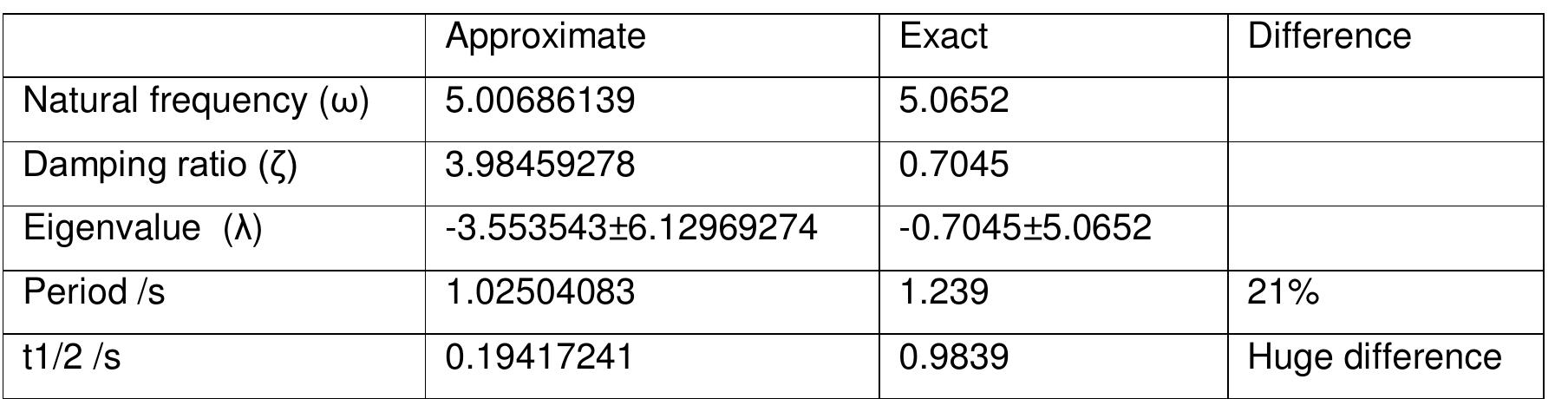
Table 6 Dutch role mode
Approximate Exact Difference
Natural frequency (ω) 5.00686139 5.0652
Damping ratio (ζ) 3.98459278 0.7045
Eigenvalue (λ) -3.553543±6.12969274 -0.7045±5.0652
Period /s 1.02504083 1.239 21%
t1/2 /s 0.19417241 0.9839 Huge difference
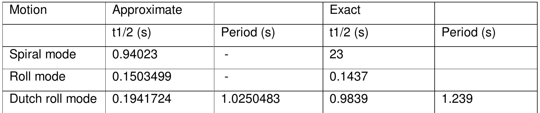
Table 7 exact and approximate comparison
Motion Approximate Exact
t1/2 (s) Period (s) t1/2 (s) Period (s)
Spiral mode 0.94023 - 23
Roll mode 0.1503499 - 0.1437
Dutch roll mode 0.1941724 1.0250483 0.9839 1.239
Modelling and Simulation of a UH-UAV dynamics 29
�School of Engineering and Technology *BEng Final Year Project Report
Long-term lateral response to roll disturbance
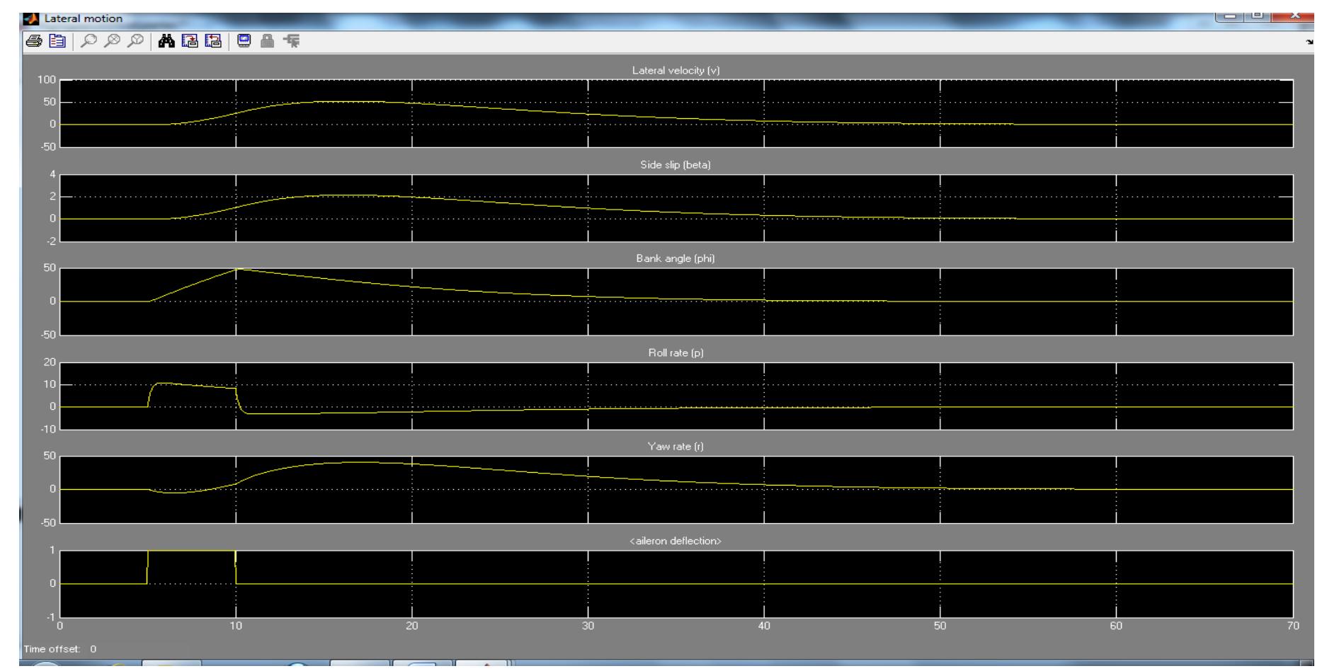
Figure 7.3.1 UAV aileron ipulse input response
The long-term response [Figure 7.3.1] shows that the MAK2 UH-UAV has positive lateral
dynamic stability. The UAV settles to zero steady state in 30s after a roll disturbance. There is
no overshoot, hence a heavily damped. This correspond predicted roll mode [Table 4]
Long-term lateral response to rudder step input.
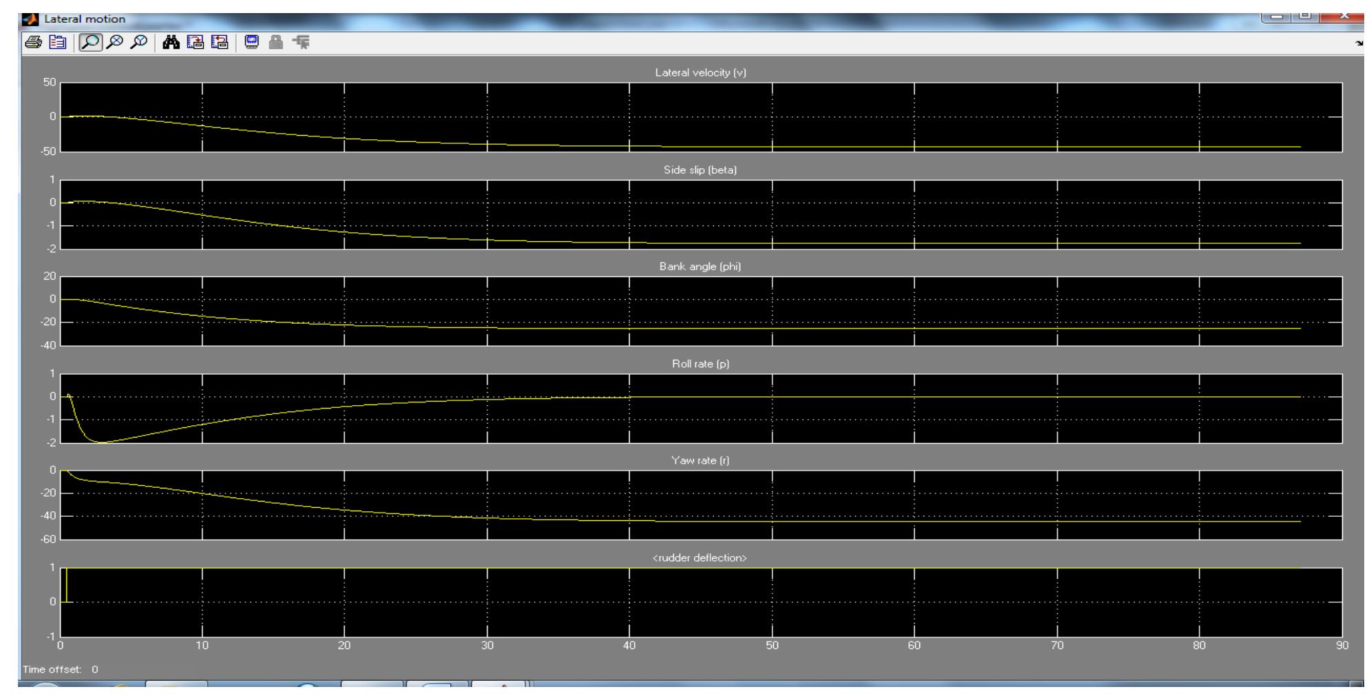
Figure 7.3.2 UAV rudder step input response
The figure 7.3.2 above shows a rudder step input response. The UAV reached a steady state
in 35s. The UAV will not return to its original sate because the rudder is left deflected.
Modelling and Simulation of a UH-UAV dynamics 30
�School of Engineering and Technology *BEng Final Year Project Report
Long-term response to lateral disturbance
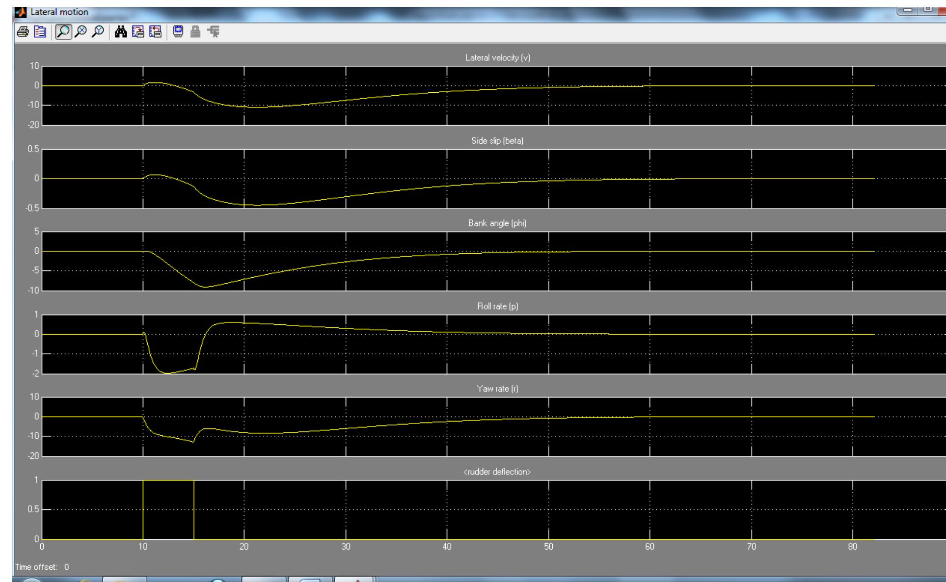
Figure 7.3.4 UAV response to yaw disturbance
8 The UAV Simulink models
This section will further analyse the Simulink model components and how they work.
8.1 Simulink Model 1
Figure 8.1.1 model 1
Modelling and Simulation of a UH-UAV dynamics 31
�School of Engineering and Technology *BEng Final Year Project Report
Longitudinal dynamics
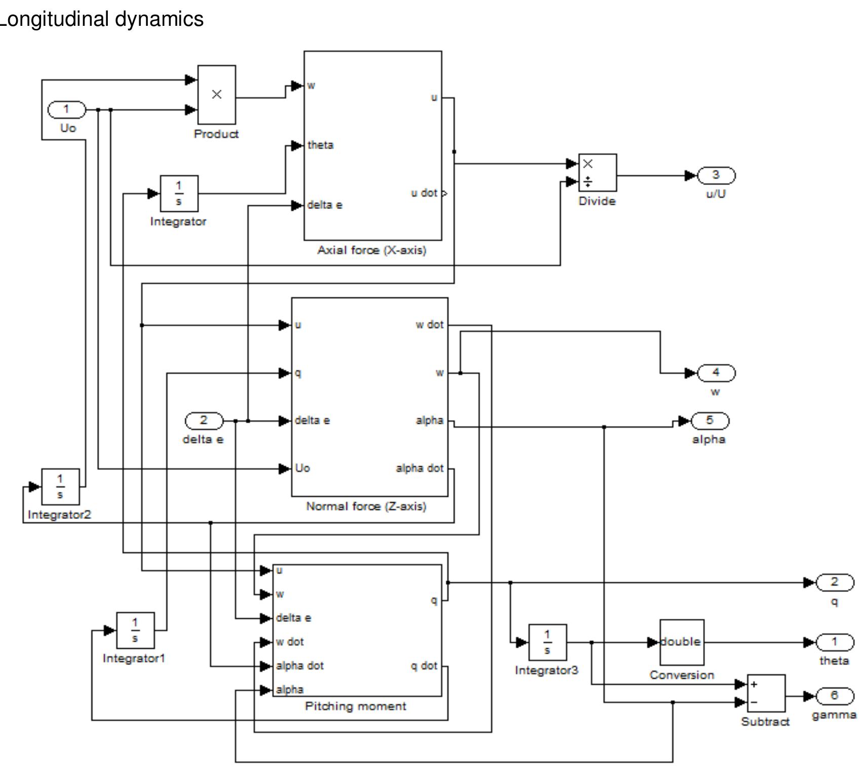
Figure 8.1.2 longitudinal dynamics
The longitudinal dynamics are calculated in the longitudinal dynamics platform. This
comprises of the axial force, Normal force and pitching moment subsystems.
The angles, rates and velocities are calculated in the subsystems.
Modelling and Simulation of a UH-UAV dynamics 32
�School of Engineering and Technology *BEng Final Year Project Report
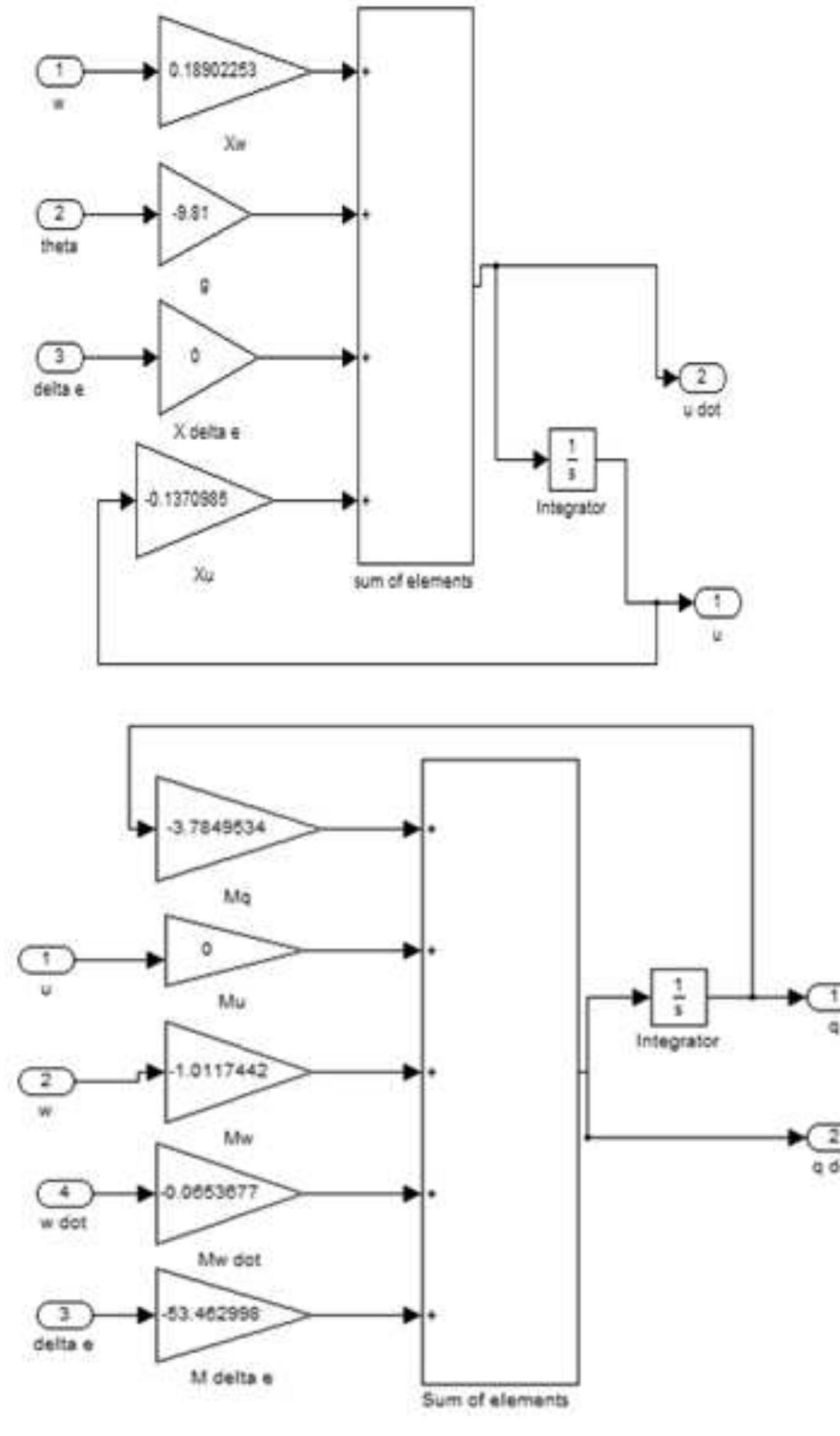
Figure 8.1.3 sum of elements X and M
Modelling and Simulation of a UH-UAV dynamics 33
�School of Engineering and Technology *BEng Final Year Project Report
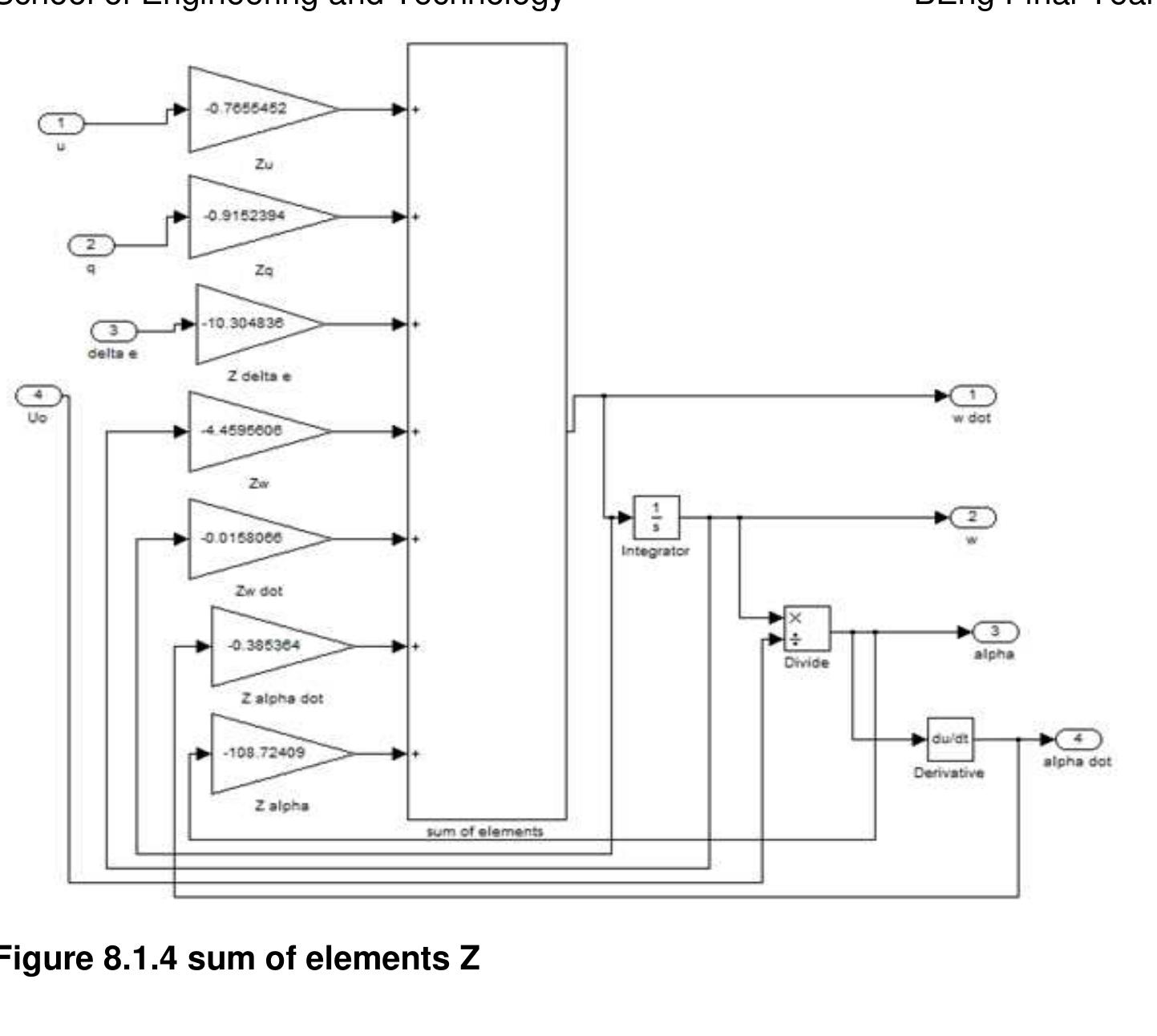
Figure 8.1.4 sum of elements Z
Lateral dynamics
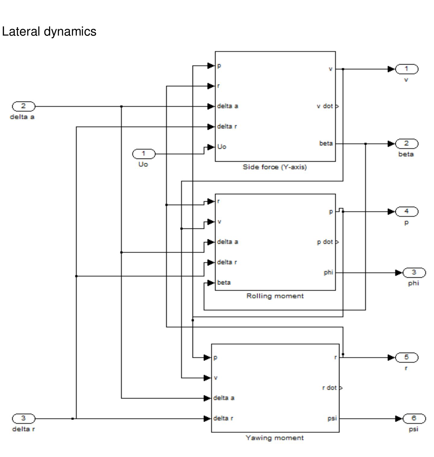
Figure 8.1.5 Lateral dynamics
Modelling and Simulation of a UH-UAV dynamics 34
�School of Engineering and Technology *BEng Final Year Project Report
The lateral dynamics are calculated in the lateral dynamics platform. This comprises of the
side force, rolling and yawing moment subsystems.
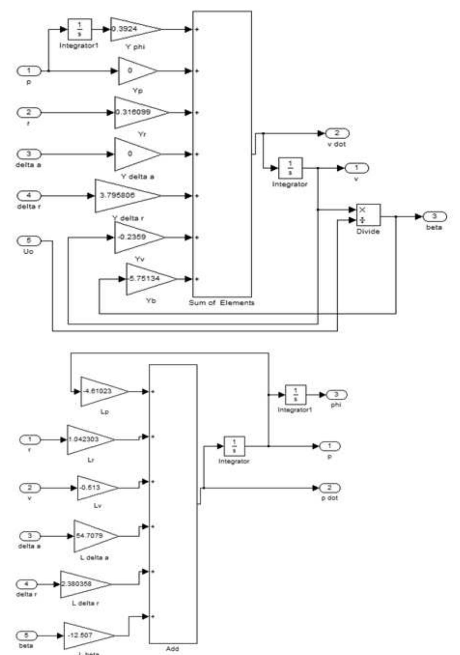
The force and moments subsystems
Figure 8.1.6 sum of elements Y and L
Modelling and Simulation of a UH-UAV dynamics 35
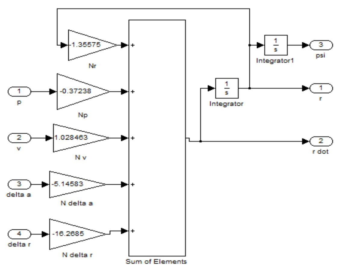
�School of Engineering and Technology *BEng Final Year Project Report
Figure 8.1.7 sum of elements N
Augmentation
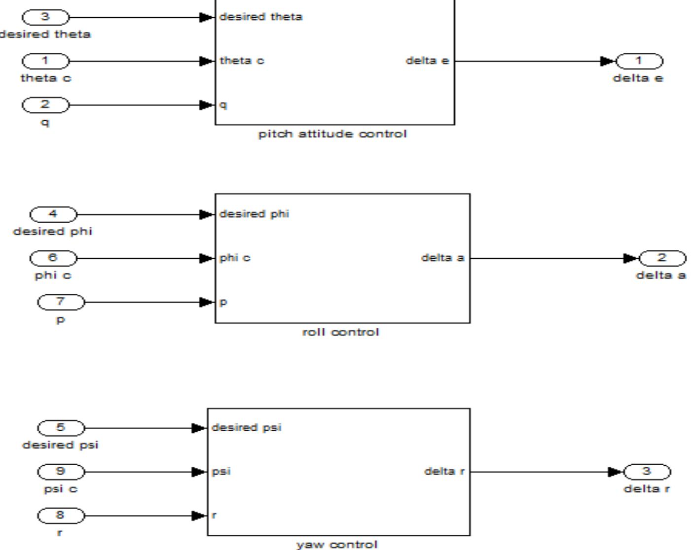
A feedback system can be introduced to the system by using the pilot platform.
The control subsystem contains gyroscope, accelerometer gains and servo actuators.
Figure 8.1.8 control platform
Modelling and Simulation of a UH-UAV dynamics 36
�School of Engineering and Technology *BEng Final Year Project Report
Visual platform
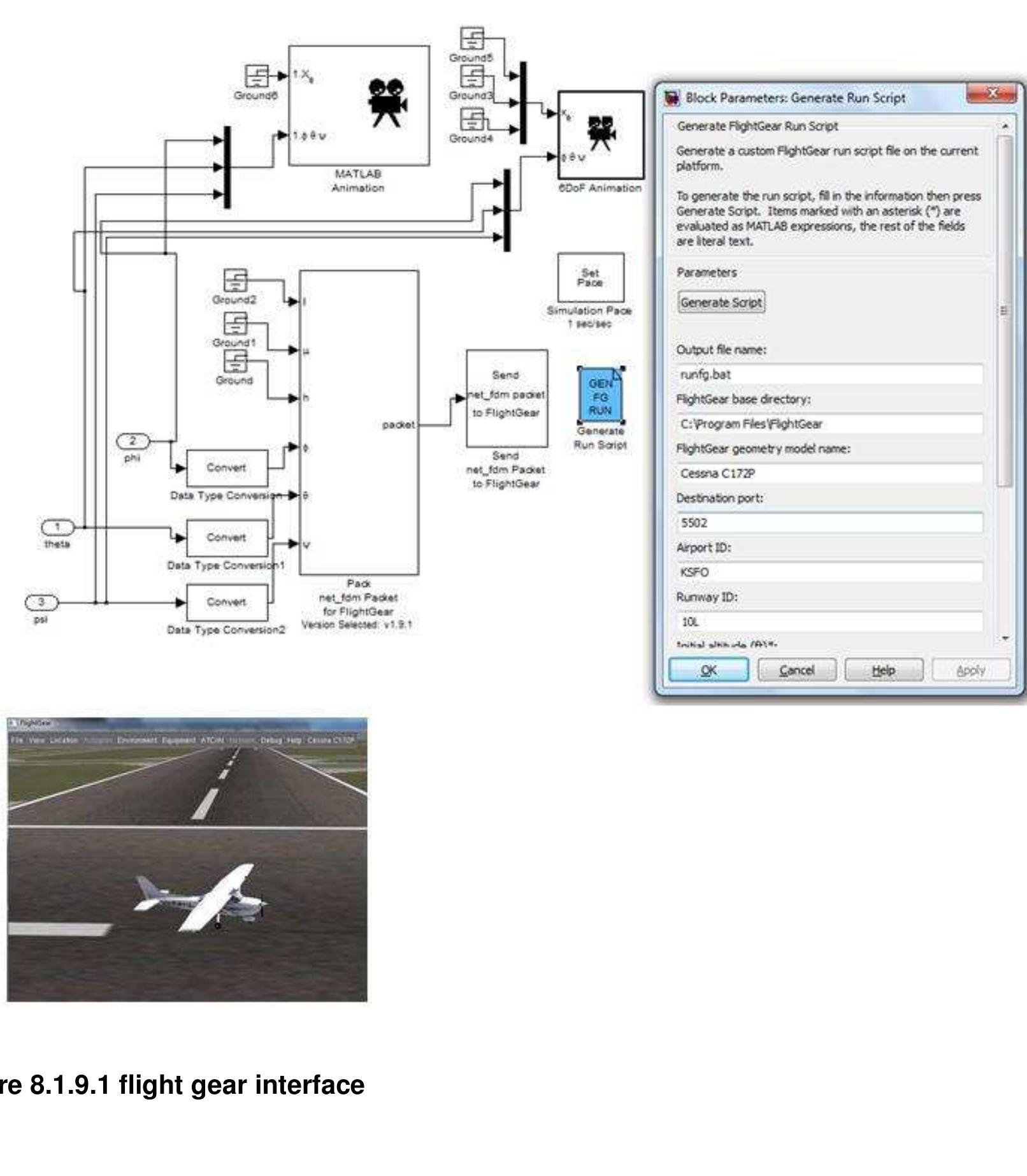
This is the flight gear interface and Matlab based animation.
Figure 8.1.9.1 flight gear interface
Modelling and Simulation of a UH-UAV dynamics 37
�School of Engineering and Technology *BEng Final Year Project Report
8.2 Simulink model 2
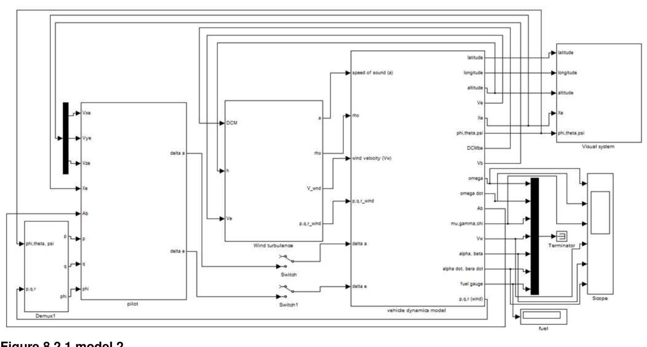
Figure 8.2.1 model 2
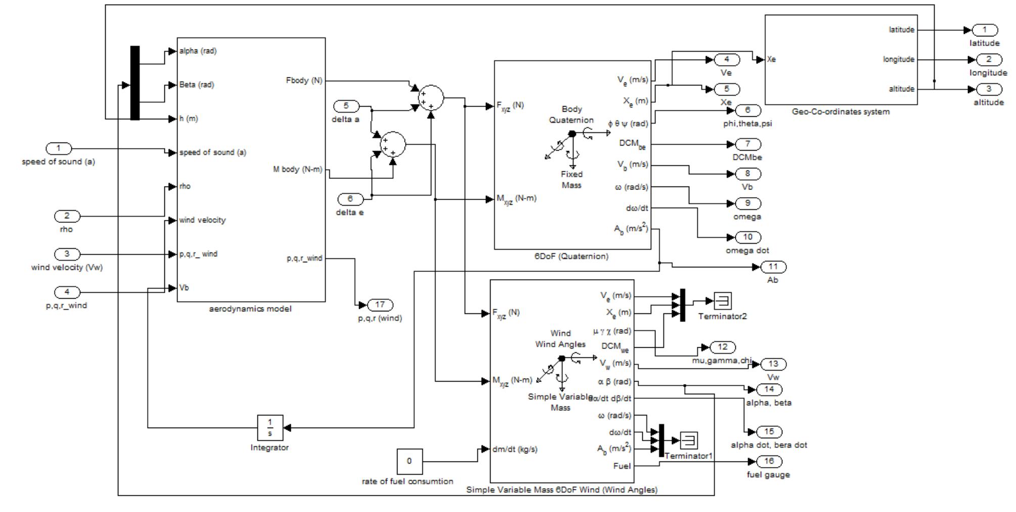
The longitudinal and lateral dynamics are calculated in the vehicle dynamics platform.
Figure 8.2.2 dynamics
The body axis is used for dynamic stability simulation and the wind axis is for mission profile
simulation.
The coordinates or position of the UAV is estimated in the geo-coordinate system from flat
earth to latitude longitude and altitude.
Modelling and Simulation of a UH-UAV dynamics 38
�School of Engineering and Technology *BEng Final Year Project Report
Figure 8.2.3 earth axis
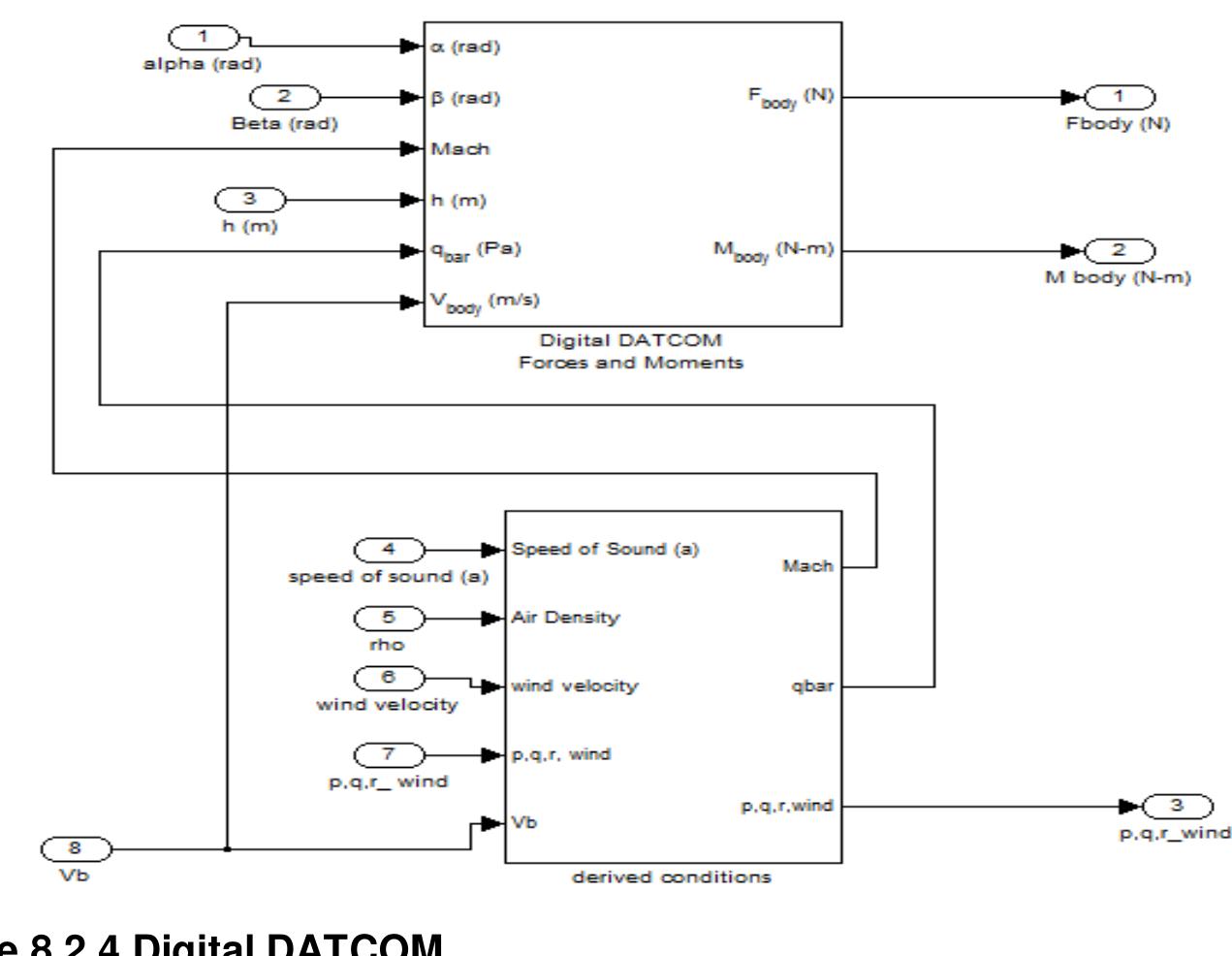
The forces and moments are calculated by the Digital DATCOM in the aerodynamic platform.
Figure 8.2.4 Digital DATCOM
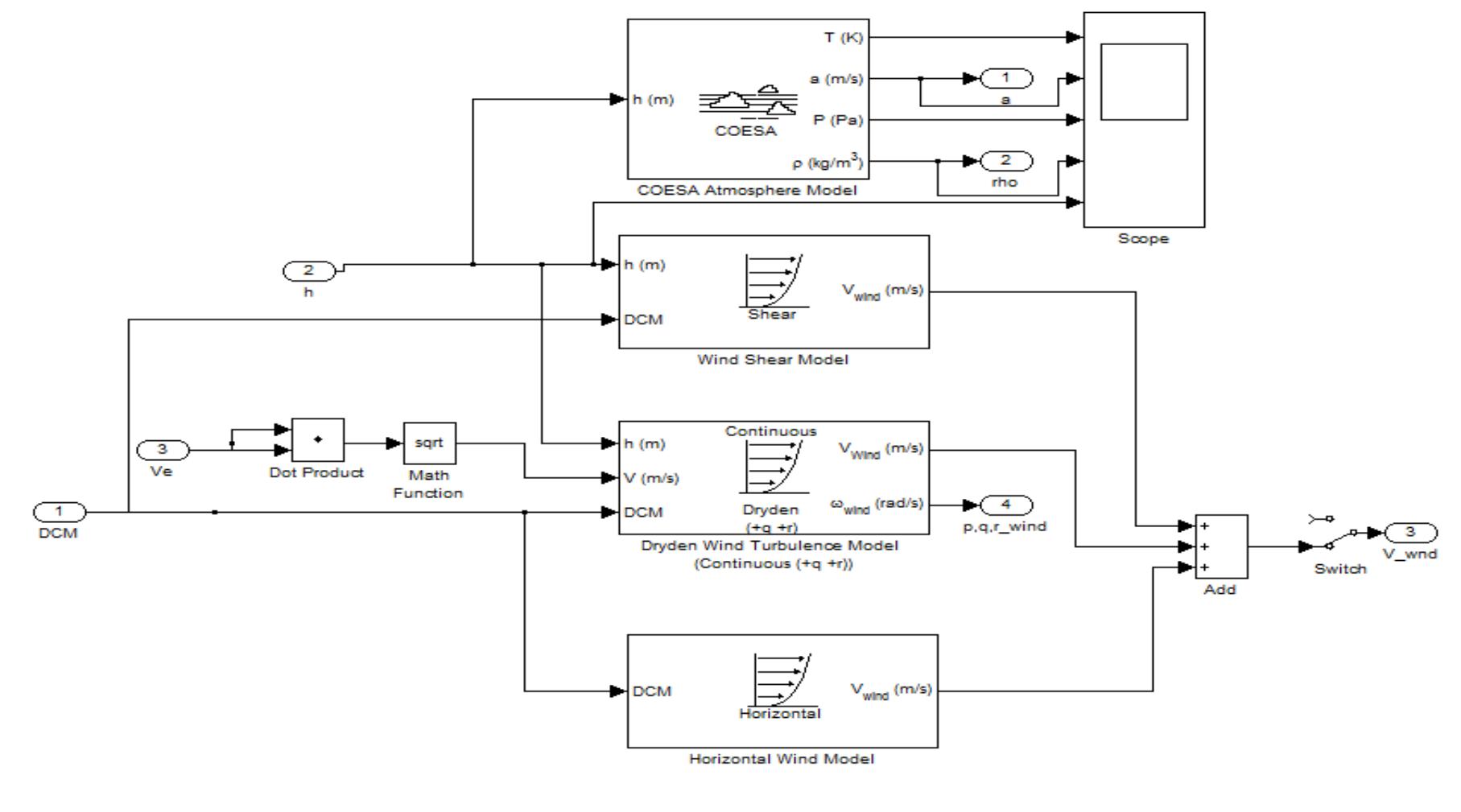
The effects atmospheric disturbances such wind Shear, turbulence and crosswinds are
computed in the turbulence platform. The COESA atmosphere model uses the geopotential
height to determine the absolute temperature, density, pressure and speed of sound at a
specific altitude.
Figure 8.2.5 Atmospheric disturbance
Modelling and Simulation of a UH-UAV dynamics 39
�School of Engineering and Technology *BEng Final Year Project Report
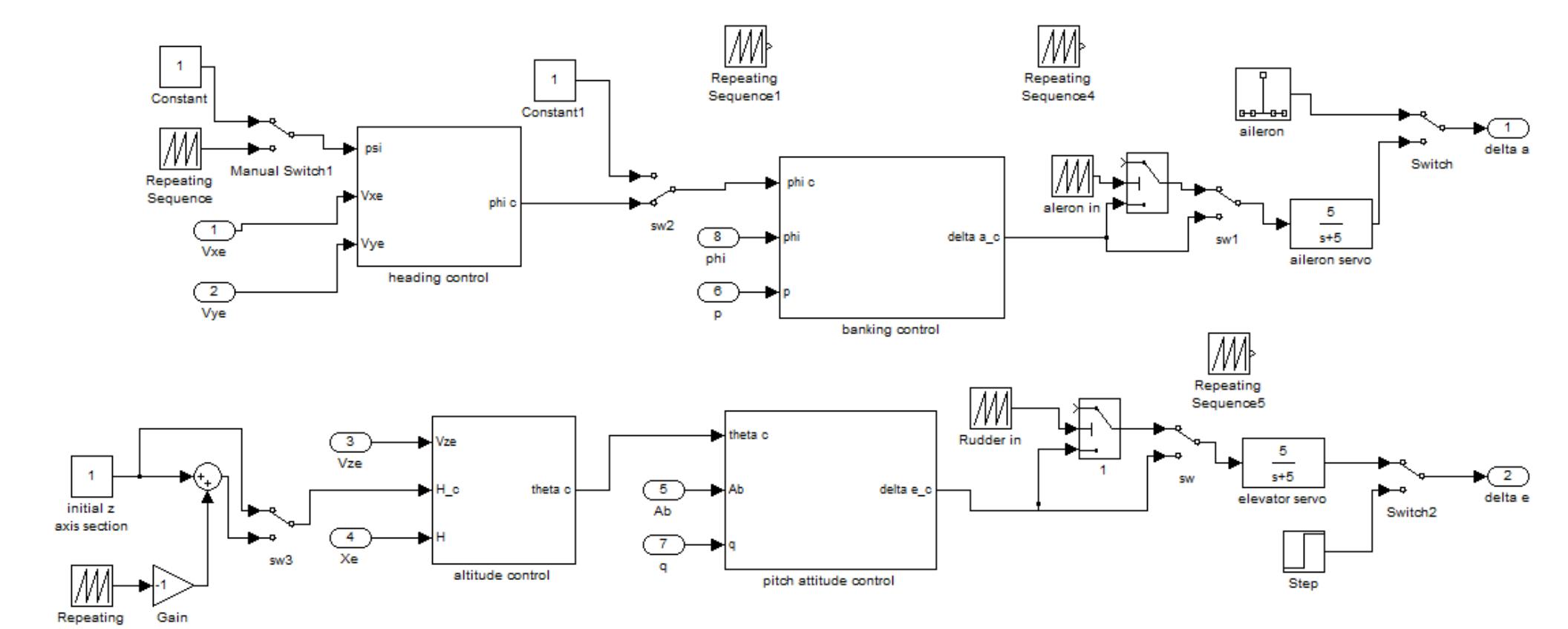
Autopilot and flight Augmentation platform
The mission can be simulated by entering the control sequences in the UAV autopilot. There
is also a feedback loop in each subsystem. This control subsystem can be used for flight
augmentation.
Figure 8.2.6 autopilot platform
Modelling and Simulation of a UH-UAV dynamics 40
�School of Engineering and Technology *BEng Final Year Project Report
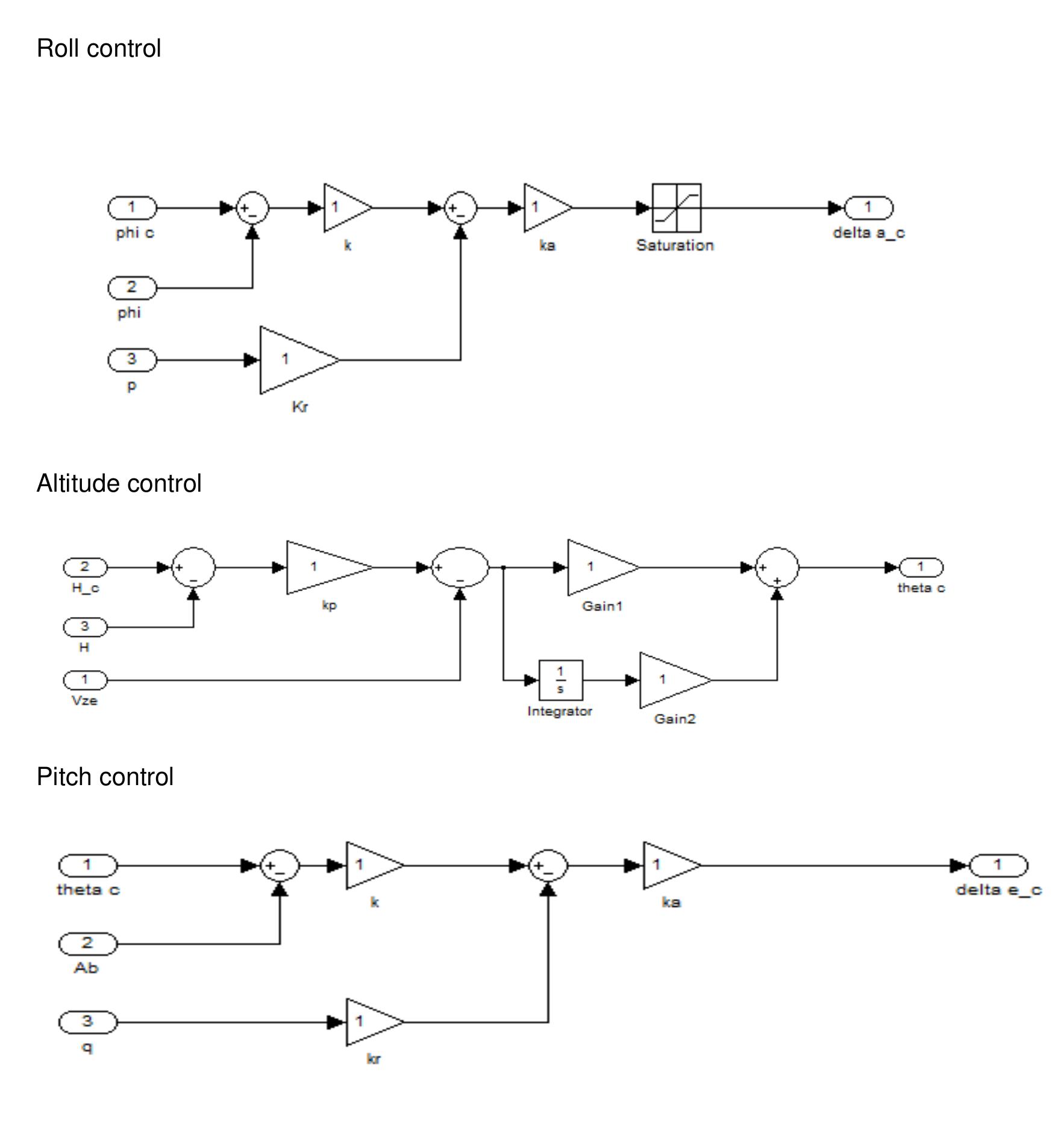
The UAV flight control subsystems.
The gains will be tuned based on the design requirements.
Heading control
Roll control
Altitude control
Pitch control
Modelling and Simulation of a UH-UAV dynamics 41
�School of Engineering and Technology *BEng Final Year Project Report
Visual platform
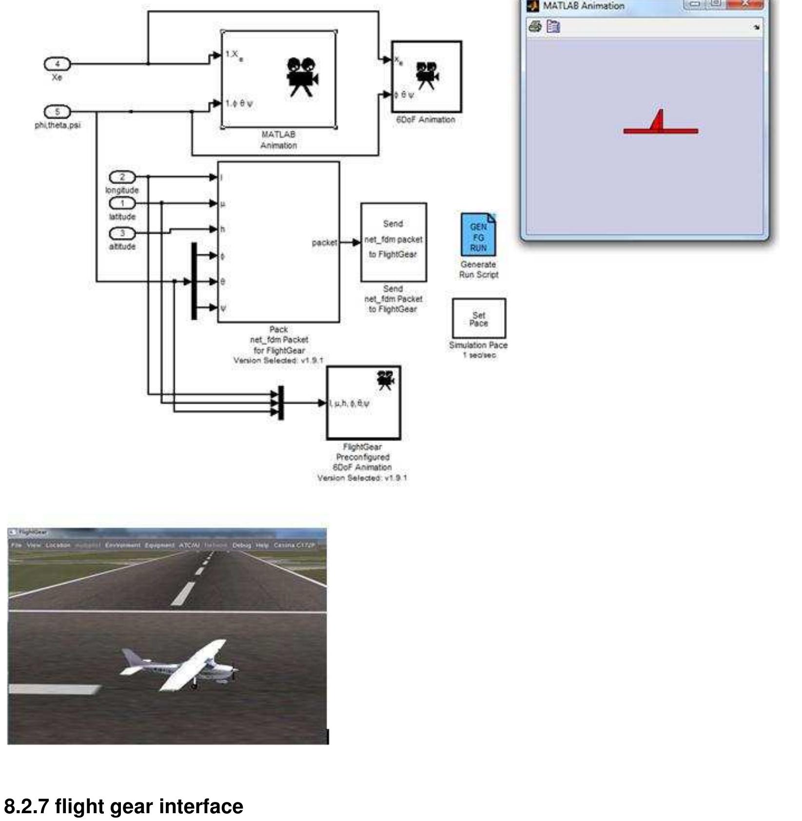
The visual platform has interface with flight gear and Matlab based animation.
Figure 8.2.7 flight gear interface
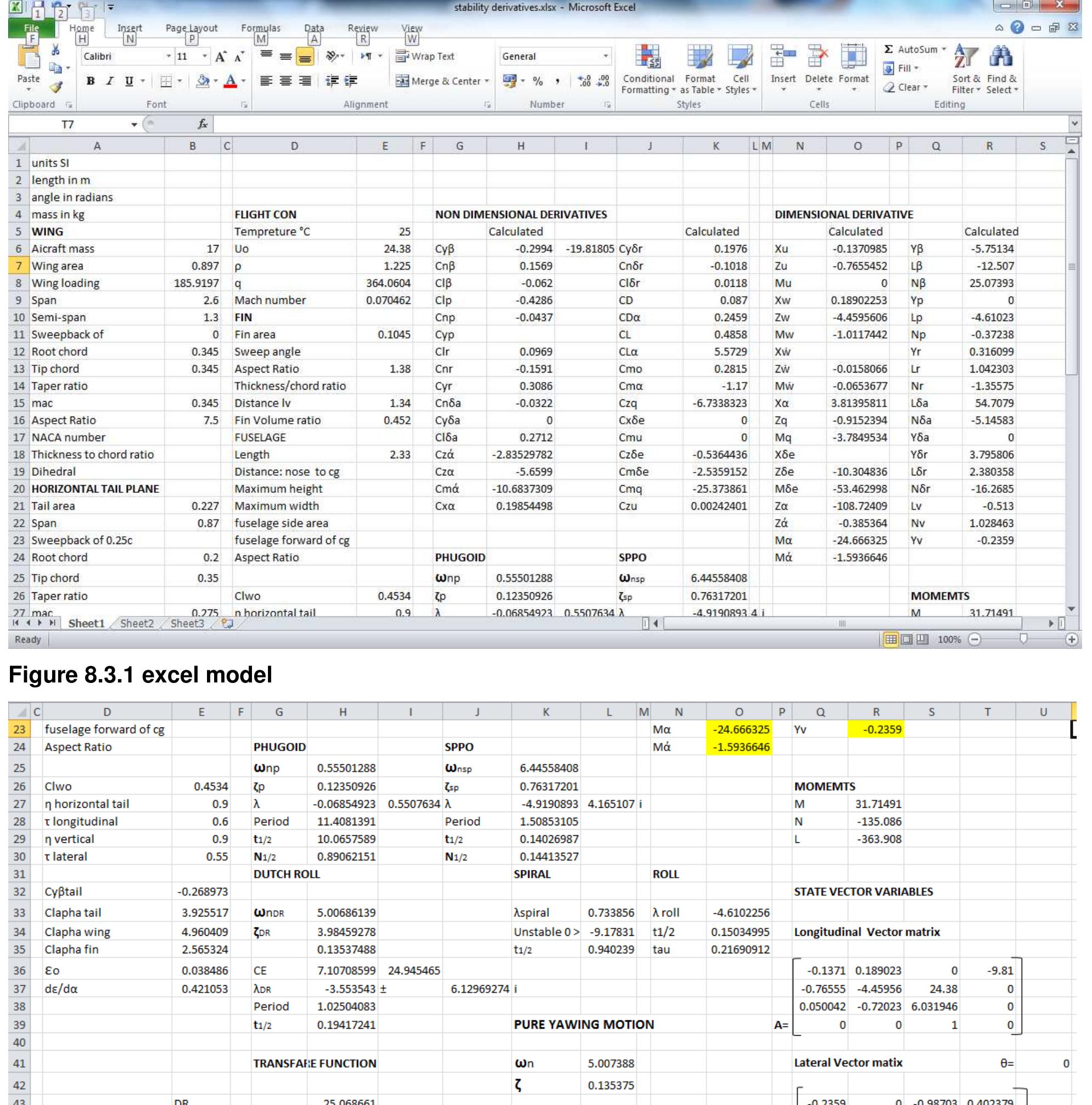
8.3 The excel model
The excel model has a section for inputting geometry parameters and flight conditions.
The data for MAK 2 UH UAV was used.
Modelling and Simulation of a UH-UAV dynamics 42
�School of Engineering and Technology *BEng Final Year Project Report
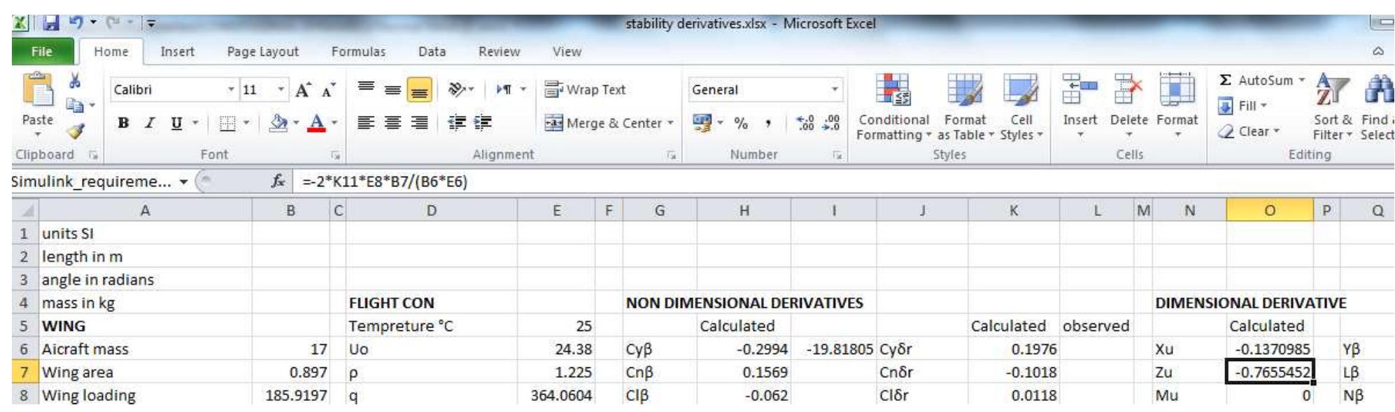
Figure 8.3.1 excel model
Figure 8.3.2 excel model
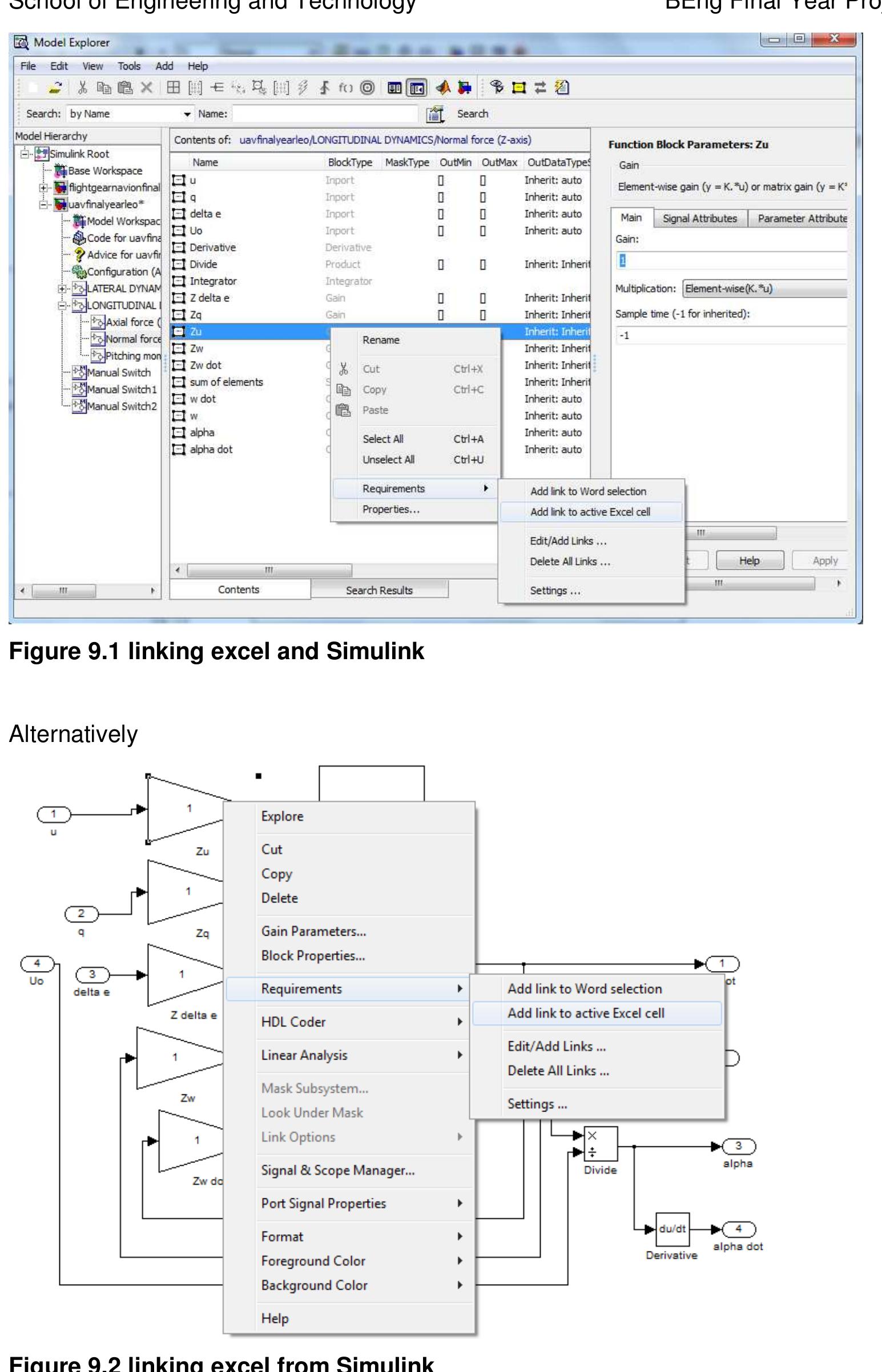
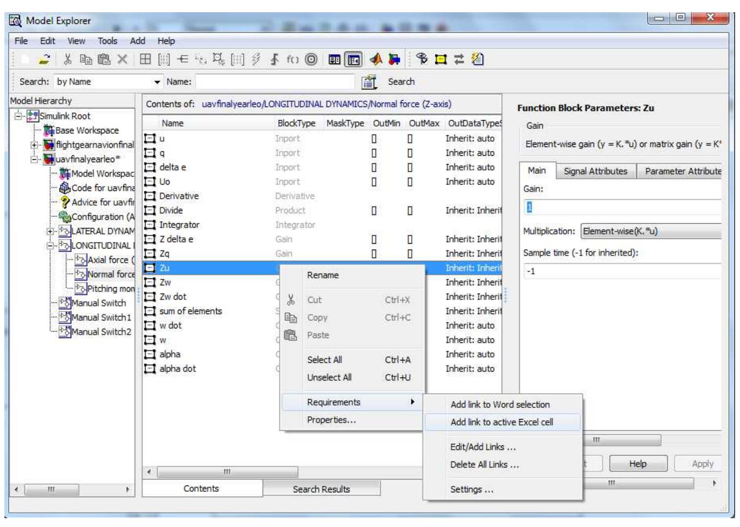
9 Linking Simulink model1 with excel model.
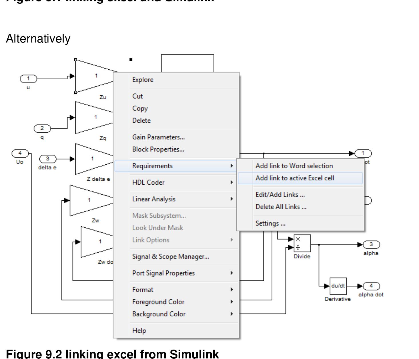
Excel model must be open and click the cell to be linked. For instants Zu, then back to
Simulink
Modelling and Simulation of a UH-UAV dynamics 43
�School of Engineering and Technology *BEng Final Year Project Report
Figure 9.1 linking excel and Simulink
Alternatively
Figure 9.2 linking excel from Simulink
Excel model actively linked to Simulink. This allows for all flight phases and flight speeds to
be simulated.
Modelling and Simulation of a UH-UAV dynamics 44
�School of Engineering and Technology *BEng Final Year Project Report
Figure 9.3 excel Simulink link
Summary
The MAK 2 UH UAV geometry data was used for the simulations.
The static and dynamic stability was defined and further analysed. The derivatives were
estimated based on the USF DATCOM method. Recommendations for an optimum UAV
geometry configuration were outlined. The derivatives and their effects on stability was
analysed in further detail. Two Simulink models were developed. Model 1 further linked to
excel and interfaced with flight-gear. This enabled all flight phases to be simulated with
automatic updates without recalculating any derivatives. Model Simulink 2 was developed to
provide both stability and mission profile simulation. It uses Digital DATCOM to calculate
derivatives. Excel model was used to validate the Simulink models by comparing the
estimated dynamic characteristics with the observed characteristics. The models can be used
to simulate any dynamics of any convectional UAV for any flight conditions. The response to
control surface inputs and atmospheric disturbances were determined. The simulations shows
that the MAK2 UH UAV has positive longitudinal dynamic stability for the given flight
conditions. The MAK2 UAV has a heavily damped SPPO mode and a lightly damped
phugoid. MAK2 UH UAV reaches equilibrium position in approximately 84 seconds after a
step elevator disturbance. The MAK2 UH UAV has positive lateral stability in roll and yaw
disturbances for the given flight conditions. The observed roll time constant was much greater
than the estimated roll time constant. Therefore the MAK2 roll rate is less responsive than
estimated. The estimation method showed that MAK2 UH UAV is unstable in spiral mode.
The research can be used by the UH UAV final year team and UH UAV society to develop an
advanced UAV capable of different missions. The stability and augmentation study can be
used to design a very stable UH UAV that can also be easily controlled. The simulations can
be used for UAV design optimisation, flight testing, and mission simulations. The model is
currently interfaced with flight gear. However for further work it can be interfaced with X-Plane
which is a more accurate flight simulation that offers flight statistical data for further analyses.
Modelling and Simulation of a UH-UAV dynamics 45
�School of Engineering and Technology *BEng Final Year Project Report
Encountered problems
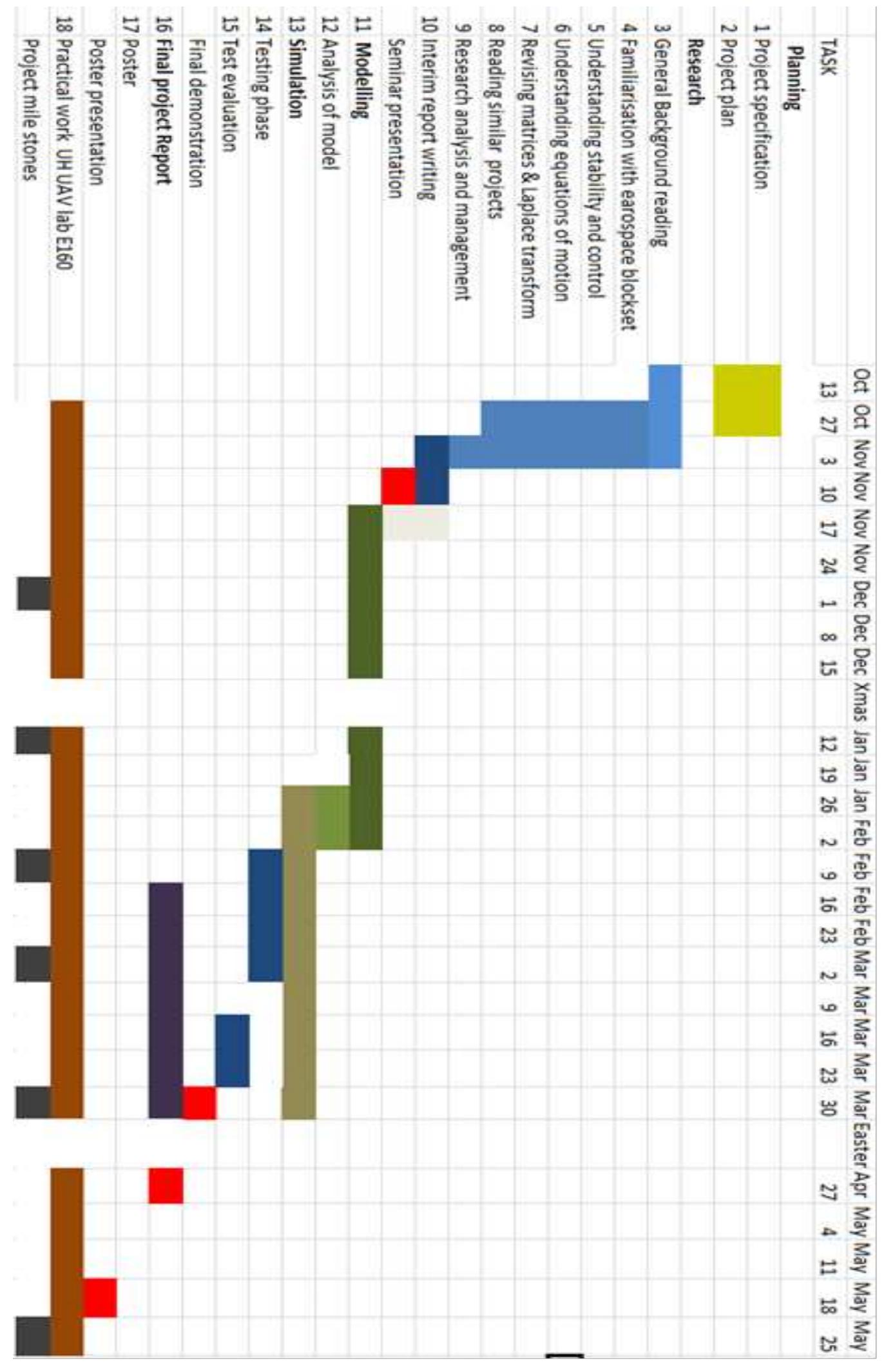
The project was run according to the time plan and it was completed on time. The main
problem was getting the data from the other UAV team members. Hence an alternative was to
use data from MAK2 an existing UH UAV. The University did not deliver the ordered materials
for the actual UAV to be built. However the stability work carried out will be a great
contribution to the UH-UAV team. I also contributed by coming up with creative solutions
such as using jigs when hotwiring. This resulted in the ailerons being completed in little time.
Time plan
Modelling and Simulation of a UH-UAV dynamics 46
�School of Engineering and Technology *BEng Final Year Project Report
References
1. Dictionary of Military and Associated Terms. US Department of Defence 2005
[viewed January 2011], available from:
http://www.thefreedictionary.com/Unmanned+Aerial+Vehicle
2. Brief History of UAVs (c) January 2003 LIST lab, University of Florida [Viewed 22
December 2010] available from: http://www.list.ufl.edu/uav/UAVHstry.htm
3. Airborne Autonomous system [Viewed 4 December 2010], available from:
http://www.unmannedaircraft.org/page/page/1357249.htm
4. Defence industry daily. An Enhanced Predator for the Army. Gray Eagle © 05
October 2010 [Viewed 22 October 2010] available from:
http://www.defenseindustrydaily.com/warrior-ermp-an-enhanced-predator-for-the-
army-03056/
5. BAE SYSTEMS Controls Develops Autopilot for Unmanned Aerial Vehicle Using
MathWorks Tools. Feng Liang © 2003 [Viewed 20 October 2010] available from:
http://www.mathworks.com/rapid-
prototyping/userstories.html?file=45510&title=BAE%20SYSTEMS%20Controls%20D
evelops%20Autopilot%20for%20Unmanned%20Aerial%20Vehicle%20Using%20Mat
hWorks%20Tools
6. Charles E. Dole, James E. Lewis Flight Theory and Aerodynamics, 2nd edition John
Wiley and Sons, 2000, 237
7. Robert C. Nelson Flight stability and Automatic control, 2nd edition McGraw-Hill: Tom
Casson,1998, 39
8. Charles E. Dole, James E. Lewis Flight Theory and Aerodynamics, 2nd edition, john
Wiley and Sons, 2000, 238
9. Charles E. Dole, James E. Lewis Flight Theory and Aerodynamics, 2nd edition, John
Wiley and Sons, 2000, 238
10. Charles E. Dole, James E. Lewis Flight Theory and Aerodynamics, 2nd edition, John
Wiley and Sons, 2000,238
11. John Hodgkinson, Aircraft Handling qualities, Blackwell Sciences,1999, 21
12. John Hodgkinson, Aircraft Handling qualities, Blackwell Science,1999, 24
13. Charles E. Dole, James E. Lewis Flight Theory and Aerodynamics, 2nd edition, John
Wiley and Sons, 2000, 245
14. Charles E. Dole, James E. Lewis Flight Theory and Aerodynamics, 2nd edition, John
Wiley and Sons,2000,245
15. Charles E. Dole, James E. Lewis Flight Theory and Aerodynamics, 2nd edition, John
Wiley and Sons, 2000, 247
16. Robert C. Nelson Flight stability and Automatic control, 2nd edition McGraw-Hill: Tom
Casson, 1989, 50
Modelling and Simulation of a UH-UAV dynamics 47
�School of Engineering and Technology *BEng Final Year Project Report
17. Robert C. Nelson Flight stability and Automatic control, 2nd edition McGraw-Hill: Tom
Casson, 1989, 50
18. Charles E. Dole, James E. Lewis Flight Theory and Aerodynamics , 2nd edition, John
Wiley and Sons, 2000, 248
19. Robert C. Nelson Flight stability and Automatic control, 2nd edition McGraw-Hill:Tom
Casson 1989, 50
20. Charles E. Dole, James E. Lewis Flight Theory and Aerodynamics, 2nd edition, John
Wiley and Sons, 2000, 248
21. Robert C. Nelson Flight stability and Automatic control, 2nd edition McGraw-Hill: Tom
Casson, 1988, 50
22. Charles E. Dole, James E. Lewis Flight Theory and Aerodynamics, 2nd edition, John
Wiley and Sons, 2000, 249
23. Robert C. Nelson Flight stability and Automatic control, 2nd edition McGraw-Hill: Tom
Casson, 1998, 63
24. Robert C. Nelson Flight stability and Automatic control, 2nd edition McGraw-Hill: Tom
Casion, 1998, 65
25. Robert C. Nelson Flight stability and Automatic control, 2nd edition McGraw-Hill: Tom
Casson,1998, 67
26. Charles E. Dole, James E. Lewis Flight Theory and Aerodynamics, 2nd edition John
Wiley and Sons, 2000, 259
27. Charles E. Dole, James E. Lewis Flight Theory and Aerodynamics, 2nd edition John
Wiley and Sons, 2000 , 264
28. Robert C.Nelson Flight stability and Automatic control, 2nd edition McGraw-Hill: Tom
Casson 1998, 65
29. Robert C. Nelson Flight stability and Automatic control, 2nd edition, McGraw-Hill: Tom
Casson,1998,81
30. Robert C. Nelson Flight stability and Automatic control, 2nd edition, McGraw-Hill: Tom
Casson, 1998, 81
31. Charles E. Dole, James E. Lewis Flight Theory and Aerodynamics, 2nd edition, John
Wiley and Sons, 2000, 274
32. Charles E. Dole, James E. Lewis Flight Theory and Aerodynamics , 2nd edition, John
Wiley and Sons, 2000, 274
33. Robert C. Nelson Flight stability and Automatic control, 2nd edition, McGraw-Hill:Tom
Casson,1998,100
34. Michael. V. Cook Flight dynamics principal, 2nd edition, Elsevier Ltd, 2007, 71
35. Robert C. Nelson Flight stability and Automatic control, 2nd edition, McGraw-Hill: Tom
Casson,1998,104
36. Aerospace systems dynamics and control Meng notes, University of Hertfordshire,
studynet, 2011
37. Level M flight Mechanics notes , Hertfordshire University, studynet , 2011
Modelling and Simulation of a UH-UAV dynamics 48
�School of Engineering and Technology *BEng Final Year Project Report
38. Michael. V. Cook Flight dynamics principal, 2nd edition, Elsevier Ltd, 2007, 381
39. Michael. V. Cook Flight dynamics principal, 2nd edition, Elsevier Ltd, 2007, 381
40. Aerospace systems,dynamics and control MEng notes, Hertfordshire University,
studynet, 2011
41. Aerospace systems dynamics and control MEng notes, Hertfordshire University
studynet, 2011
42. Aerospace systems dynamics and control MEng notes, Hertfordshire University
studynet, 2011
43. Aerospace systems dynamics and control MEng notes, Hertfordshire University ,
studynet, 2011
44. Michael. V. Cook Flight dynamics principal, 2nd edition, Elsevier Ltd, 2007, 384
45. Michael. V. Cook Flight dynamics principal, 2nd edition, Elsevier Ltd, 2007, 384
46. Introduction to aircraft stability and control 2 ASE4 notes, University of Hertfordshire
studynet, 2011
47. Introduction to aircraft stability and control 2 ASE4 notes, University of Hertfordhsire
studynet, 2011
48. Robert C. Nelson Flight stability and Automatic control, 1st edition, McGraw-Hill,
1989,159
49. Robert C. Nelson Flight stability and Automatic control,1st edition, McGraw-Hill,
1989,162
50. Robert C. Nelson Flight stability and Automatic control, 1st edition, McGraw-Hill,
1989,162
51. Robert C. Nelson Flight stability and Automatic control, 1st edition, McGraw-Hill,
1989,181
52. Introduction to aircraft stability and control 2 ASE4 notes, University of Hertfordshire
studynet, 2011
53. Introduction to aircraft stability and control 2 ASE4 notes, University of Hertforshire
studynet,2011
54. Robert C. Nelson Flight stability and Automatic control, 1st edition, McGraw-Hill,
1989,198
55. Robert C. Nelson Flight stability and Automatic control, 1st edition, Mc Graw-Hill,
1989,198
56. Robert C. Nelson Flight stability and Automatic control, 2nd edition, Mc Graw-Hill,
1989,231
Modelling and Simulation of a UH-UAV dynamics 49
�School of Engineering and Technology *BEng Final Year Project Report
Bibliography
1. Accelerating the space of engineering and science, Aerospace and defence
www.mathworks.com/aerospace-defense/
2. Stevens, B. L., and F. L. Lewis, Aircraft Control and Simulation, John Wiley & Sons,
New York, 1992.
3. Smetana, F.O., Computer assisted analysis of aircraft performance stability and
control, McGraw-Hill 1984.
4. Babister A.W, Aicraft Dynamics Stability and Response, Pergamon Press, 1980
5. Etkin B, Reid L.D, Dynamics of flight stability and control, 3rd edition, John Wiley and
Sons
6. Schmidt L.V, Introduction to aircraft flight dynamics, American Institute of Aeronautics
and astronautics, 1998
7. Miller M.P, Accurate method of measuring the moments of Inertia of airplanes,
National Advisory Committee for Aeronautics, Washington October 1930.
8. Roskan J, Aiplane Flight Dynamics and Automatic control, 3rd edition, 2001.
DARcorporation
9. Turevskiy A, Gage S, Buhr C , Model-Based Design of a New Light-weight
Aircraft.The MathWorks, Inc. Natick, MA, 01760
10. Mathworks Matlab help file
All the equations used for this project can be obtained from the following books
List in order of importance
1. Flight stability and Automatic control, 2nd edition, Mc Graw-Hill by Robert C. Nelson
2. Flight dynamics principal, 2nd edition, Elsevier Ltd, 2007 by Michael .V .Cook
3. Aircraft handling qualities 1st edition, Blackwell Science Ltd , 1999 by John
Hodgkinson
Modelling and Simulation of a UH-UAV dynamics 50
�School of Engineering and Technology *BEng Final Year Project Report
APPENDICES
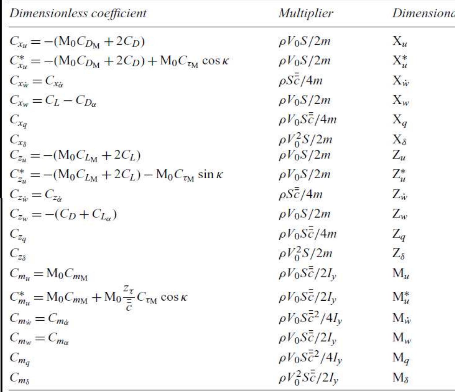
APPENDIX A: The longitudinal derivative estimation equations
Copy obtained from
Michael. V. Cook Flight dynamics principal, 2nd edition, Elsevier Ltd, 2007, 431
Modelling and Simulation of a UH-UAV dynamics 51
�School of Engineering and Technology *BEng Final Year Project Report
APPENDIX B: Lateral derivative equations
Copy obtained from
Robert C. Nelson Flight stability and Automatic control, 1st edition, Mc Graw-Hill, 1989,108
Copy obtained from
Michael. V. Cook Flight dynamics principal, 2nd edition, Elsevier Ltd, 2007, 432
Modelling and Simulation of a UH-UAV dynamics 52
�School of Engineering and Technology *BEng Final Year Project Report
APPENDIX C: Eigen vector for gust
Modelling and Simulation of a UH-UAV dynamics 53
�


 Leonine Kunzwa